Direction-agile antenna system for wireless communications

An antenna system and antenna technology, applied in wireless communication, diversity/multi-antenna system, antenna, etc., can solve the problems of complex data transmission and reception of equipment, unfixed position of communication equipment, etc., to avoid RF power and maintain instant communication , to achieve the effect of high-speed data transmission

Inactive Publication Date: 2007-07-25
爱尔格公司
View PDF2 Cites 4 Cited by
  • Summary
  • Abstract
  • Description
  • Claims
  • Application Information

AI Technical Summary

Problems solved by technology

[0004] Furthermore, in a typical mobile wireless network, at least some of the communicating devices are not fixed to each other, thus complicating the transmission and reception of data by different devices within the network

Method used


Image

  • Direction-agile antenna system for wireless communications
  • Direction-agile antenna system for wireless communications
  • Direction-agile antenna system for wireless communications

Examples


Embodiment Construction

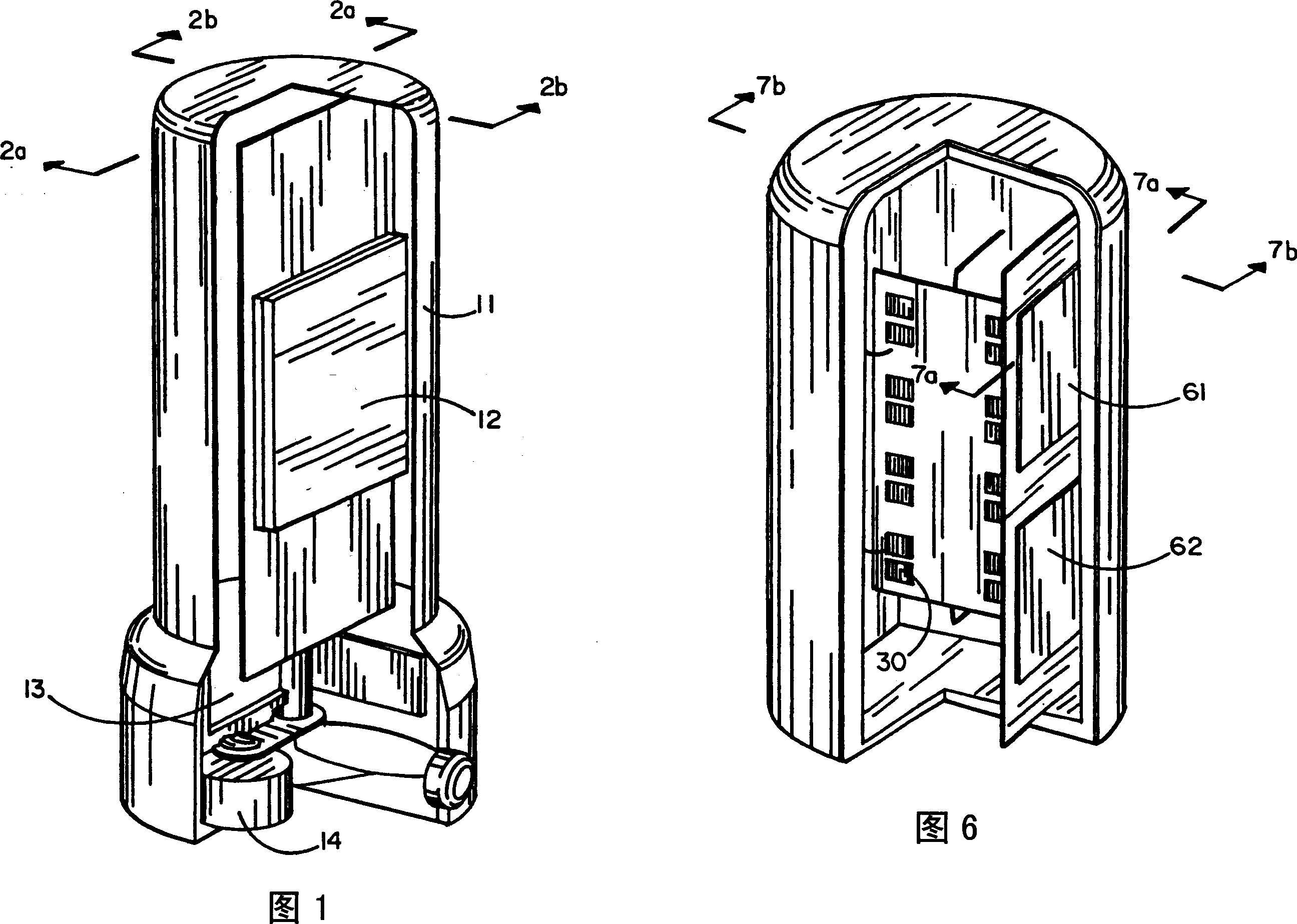
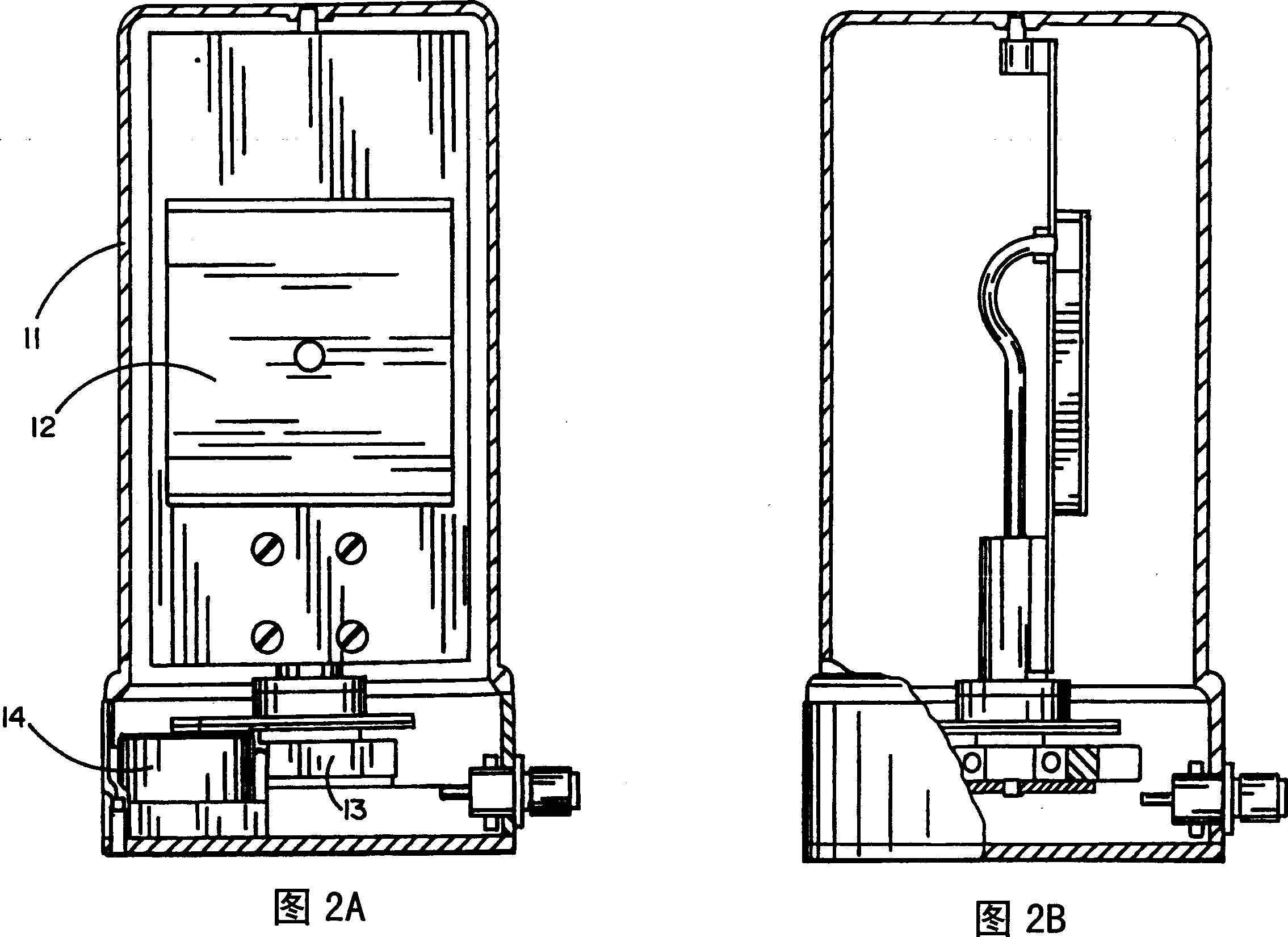
[0023] Figure 1 is a perspective view, partly cut away, of an example of a steerable antenna system for use in a mobile wireless communication network. In this embodiment, the antenna system includes a mechanically steered antenna 12 enclosed in a dielectric housing, and a motor drive 13 coupled to a motor 14 which rotates the antenna into a desired orientation. In an embodiment, the motor 14 is capable of rotating the antenna 12 through 360° in the horizontal plane to scan the antenna beam. In another embodiment, the motor 13 can drive the antenna to scan in both azimuth and height directions.

[0024] In an embodiment, the antenna 12 is a planar microstrip antenna, which includes a group of microstrip antenna elements that can transmit and receive electromagnetic signals in the direction of a positive gain antenna, and other types of positive gain antennas can also be within the scope of the present invention Realize the direction variable antenna system, for example, parab...


PUM


Abstract

A direction-agile antenna system is implemented in a wireless network to allow wireless communication devices to establish and maintain wireless data links with each other. In one embodiment the antenna is provided with a motor and a step motor drive for rotating the antenna to the selected direction. In other embodiment the antenna comprises an array of antennas capable of electronically steering the electromagnetic signal to the selected direction.

Description

field of invention [0001] The present invention relates to an antenna system, in particular to an antenna system for communication in a wireless network. Background technique [0002] In general wireless networks, omnidirectional antennas have been implemented in various mobile communication devices, for example, digital mobile phone networks. In addition to voice communication, it is also used for various devices such as desktop computers, laptops, servers, peripherals in wireless networks and power management hubs. Much effort has been devoted to high-speed data communications among the Internet of Things, which typically require large bandwidths, extremely low bit error rates, and the ability to communicate with multiple devices at different locations compared to voice communications. [0003] In a general antenna network, in order to ensure high-speed data transmission with an extremely low bit error rate, a high RF signal-to-noise ratio (SNR) is required to transmit da...

Claims


Application Information

Patent Timeline
Patent Type & Authority Applications(China)
IPC IPC(8): H01Q3/02H01Q3/26H01Q19/00H04B1/40H04B7/10H04L12/28H01Q1/22
CPCH01Q3/02H04W76/02H01Q1/22H01Q1/2275H01Q3/26H01Q1/2258H04W76/10
Inventor 奥列格·Y·阿布罗莫夫亚历山大·G·卡什卡罗夫亚历山大·N·基尔金
Owner 爱尔格公司
Why Eureka
Try Eureka