
Permanent magnet synchronous motor

A permanent magnet synchronous, motor technology, applied in the direction of magnetic circuit rotating parts, magnetic circuit shape/style/structure, manufacturing stator/rotor body, etc. The problem of low multiples can improve the axial ventilation effect, reduce the vibration phenomenon, and reduce the demagnetization intensity.

Active Publication Date: 2007-07-25
北京佐腾达制冷空调设备有限公司 +1
View PDF0 Cites 14 Cited by
  • Summary
  • Abstract
  • Description
  • Claims
  • Application Information

AI Technical Summary

Problems solved by technology

[0002] At present, Y series asynchronous motors are mostly used in the industrial field, which has low efficiency, poor power factor, low starting torque multiple, and serious waste of energy.
However, various rare earth permanent magnet synchronous motors successfully developed in recent years, including permanent magnet synchronous motors using conventional laminated magnetic pole rotors and solid magnetic pole rotors, generally speaking, still have the problem of small starting torque, and the starting torque multiple is only 2.2 to 2.7 times, while the starting current multiple is as high as 7 to 9 times
Mostly fall short of what one would expect from an efficient motor
[0003] In addition, at present, many types of permanent magnet motors will have a phenomenon of overall performance degradation due to demagnetization of the magnetic steel shortly after industrial operation.

Method used


Image

  • Permanent magnet synchronous motor
  • Permanent magnet synchronous motor
  • Permanent magnet synchronous motor

Examples


Embodiment 1

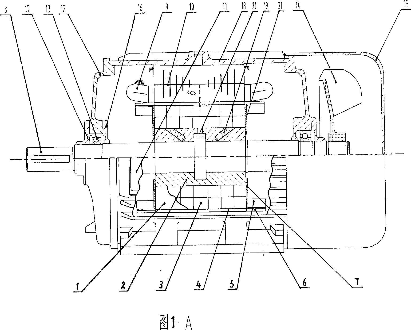
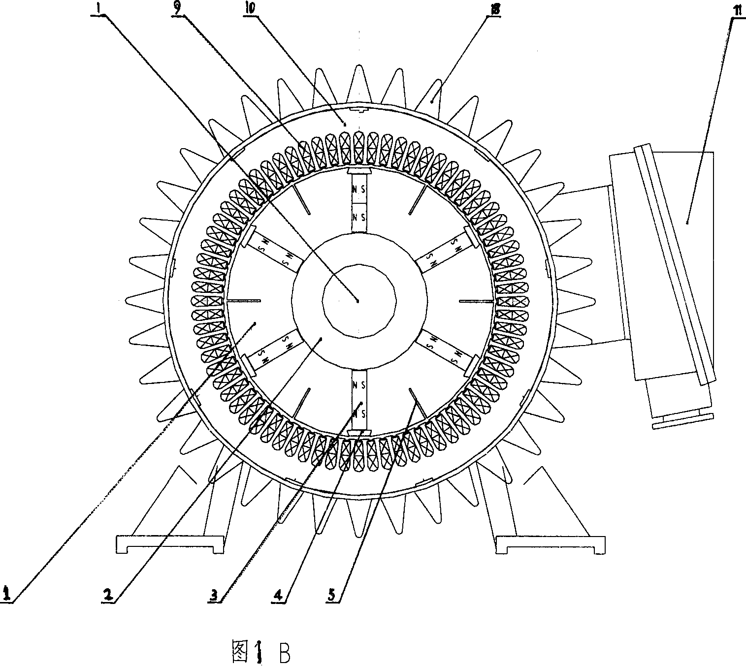
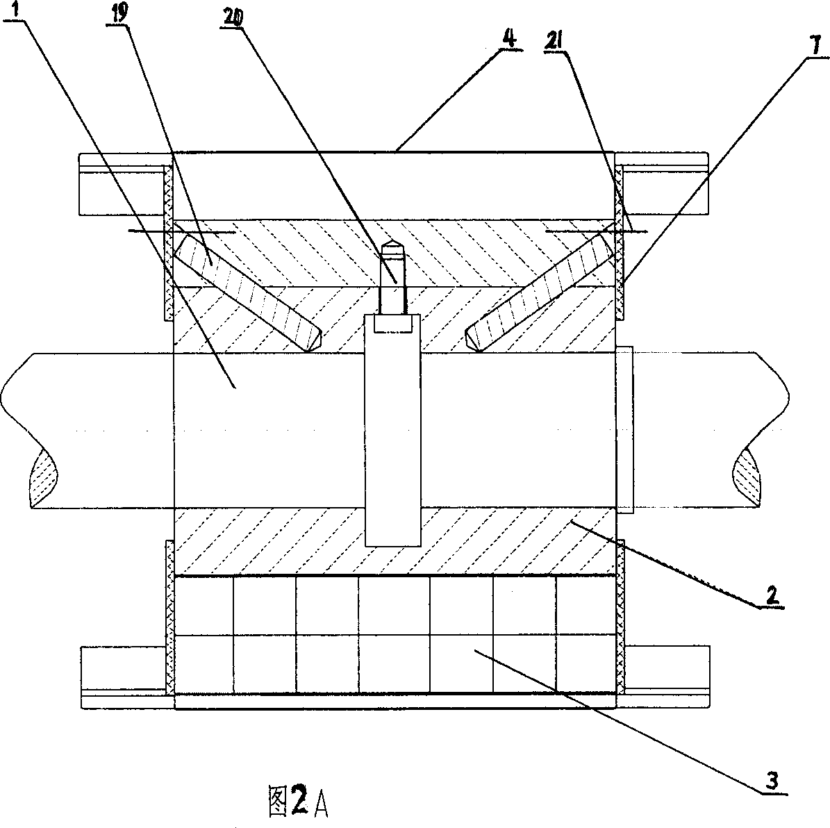
[0071] The permanent magnet synchronous motor with rare earth NdFeB excitation of the present invention has a capacity of 15KW, and its large air gap δ m Ratio to the minimum air gap δ: δ m / δ=1.7 / 1.7 (as shown in Figure 1); polar arc coefficient α=0.84; copper end ring thickness × width is 3 × 40 (mm); central small groove width / height is 1.5mm / 26mm (Figure 3A); each A permanent magnet a × b × h is 19mm × 20mm × 12mm. The ratio of the side length a of the rectangular block to the thickness h in the direction of magnetization is a / h≤2.5 (Figure 6).

Embodiment 2

[0073] The permanent magnet synchronous motor with rare earth NdFeB excitation of the present invention has a capacity of 45KW, and its large air gap δ m Ratio to the minimum air gap δ: δ m / δ=2.9 / 2.9 (as shown in Figure 1); polar arc coefficient α=0.845; copper end ring thickness × width is 3 × 45 (mm); central small groove width / height is 2mm / 32mm (Figure 3B); each The permanent magnet a×b×h is 28mm×30.8mm×20mm. The ratio of the side length a of the rectangular block to the thickness h in the direction of magnetization is a / h≤2.5 (Figure 6).

Embodiment 3

[0075] The permanent magnet synchronous motor with rare earth NdFeB excitation of the present invention has a capacity of 315KW, and its large air gap δ m Ratio to the minimum air gap δ: δ m / δ=4.2 / 6.1 (as shown in Figure 1); polar arc coefficient α=0.82; copper end ring thickness × width is 4 × 55 (mm); central small groove width / height is 4mm / 40mm (Figure 3C); each The permanent magnet a×b×h is 39.4mm×39.4mm×32.8mm. The ratio of the side length a of the rectangular block to the thickness h in the direction of magnetization is a / h≤2.5 (Figure 6).


PUM


Abstract

Following structures are adopted in the electromotor of rare earth permanent magnet: slotted solid pole, extension duplex start-up cage, pole core with large polar arc, large even air gap or heteropic air gap, small rectangle block of permanent magnet embedded to slot. Comparing with conventional permanent magnet motor of laminated pole, the basic series of permanent magnet synchronous motor possesses advantages: obviously raised starting torque 2.2-3.7, and asynchronous motor as 1.8-2.0; raised capability rank, for example it is possible to use 22kW permanent magnet motor to replace asynchronous motor in 30kWY series so as to obtain energy saving effect; start up current 5-7 times of the disclosed motor is smaller than start up current of asynchronous motor; moreover, shorter start up current, and no severe oscillation phenomenon. The basic series also overcomes difficult problem of demagnetization of neodymium - iron - boron permanent magnet electromotor.

Description

Technical field [0001] The invention relates to a permanent magnet synchronous motor, in particular to a rare earth NdFeB excited permanent magnet synchronous motor, the power range of which covers various specifications of six poles from 5.5kw to 315kw. Background technique [0002] At present, Y series asynchronous motors are mostly used in industrial fields, which have low efficiency, poor power factor, low starting torque multiple, and serious waste of energy. However, various rare earth permanent magnet synchronous motors successfully developed in recent years, including permanent magnet synchronous motors using conventional laminated magnetic pole rotors and solid magnetic pole rotors, generally speaking, still have the problem of small starting torque, and the starting torque multiple is only 2.2 to 2.7 times, while the starting current multiple is as high as 7 to 9 times. Most of them fall short of what is expected of an efficient motor. [0003] In addition, many ...

Claims


Application Information

Patent Timeline
IPC IPC(8): H02K1/27H02K15/03
Inventor 吴伟康
Owner 北京佐腾达制冷空调设备有限公司
Learn More