Vehicle body structure
A structure and body technology, applied to vehicle components, substructure, superstructure, etc., can solve problems such as complex structure, achieve simple structure, suppress deformation, and reduce repair costs
- Summary
- Abstract
- Description
- Claims
- Application Information
AI Technical Summary
Problems solved by technology
Method used
Image

Examples
no. 1 example
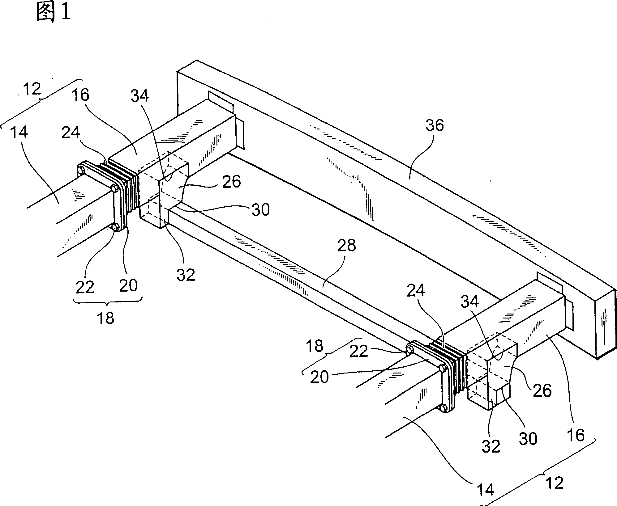
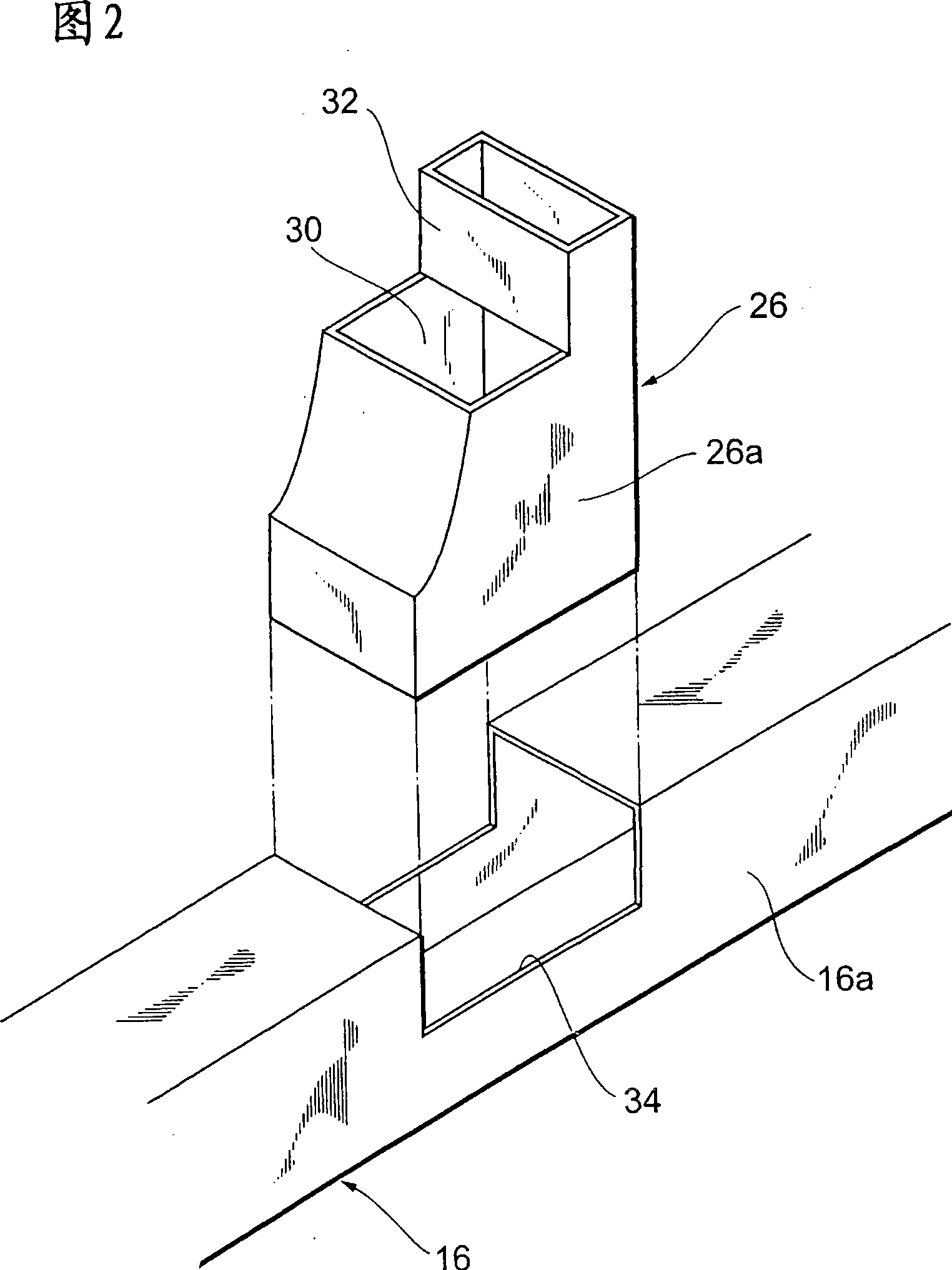
[0040] FIG. 1 is a perspective view showing main parts of a front structure of a vehicle body of an automobile according to a first embodiment. As shown in FIG. 1 , a pair of front frame rails 12 extending in the front-rear direction of the vehicle body are provided on both left and right sides of the front of the vehicle body. The front frame rail 12 has a body portion 14 and a front end portion 16 .
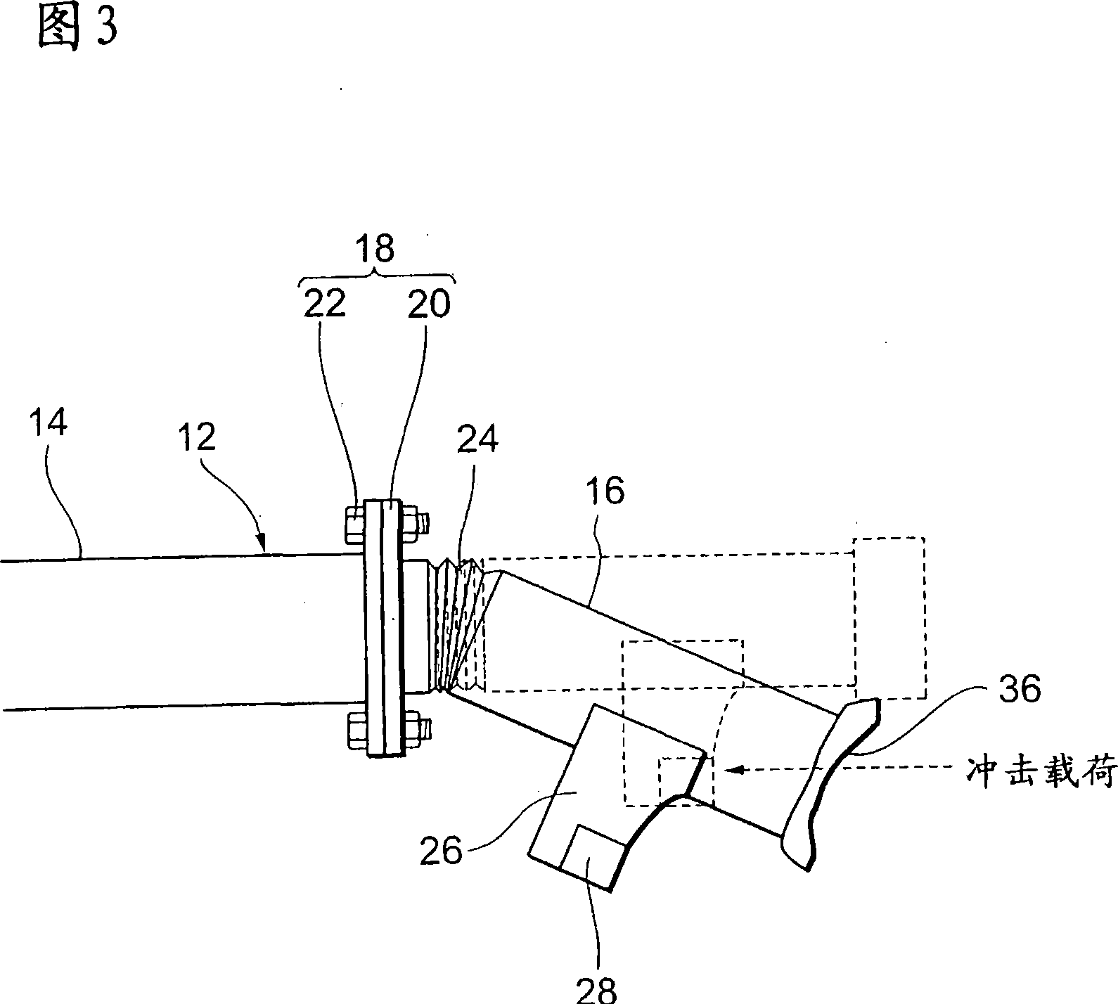
[0041] The main body portion 14 and the front end portion 16 are respectively hollow members having a square-shaped cross section. The main body portion 14 and the front end portion 16 are connected at a connection portion 18 . The connecting portion 18 has outward facing flanges 20 respectively provided on the body portion 14 and the front end portion 16 , and a bolt and nut mechanism 22 passing through the flanges 20 for fastening. The front end portion 16 is constituted by a crush box so that its resistance to axial compressive load is smaller than that of the main body po...
no. 2 example
[0053] Next, a second embodiment of the present invention will be described. The same reference numerals are assigned to the same components as those in the first embodiment described above, and redundant descriptions will be omitted.
[0054] In the front structure of the vehicle body according to this embodiment, the front frame rail 12 has a main body portion 14 and a front end portion (outer end portion) 16, which is the same as that of the above-mentioned first embodiment, but the bent portion 24 is not the first Unlike the first embodiment, the rope-shaped reinforcing rib in the embodiment is formed of the connecting portion 18 between the main body portion 14 and the front end portion 16 .
[0055] More specifically, by adjusting the breaking strength of the bolt and nut mechanism 22 and the flange 20, the connecting force at the connecting portion 18 is adjusted, and the bending strength in the front-back direction of the hanging member 26 is set to be higher than that...
no. 3 example
[0063] FIG. 11 is a schematic configuration diagram showing a vehicle structure according to a third embodiment of the present invention.
[0064] As shown in FIG. 11 , the vehicle body structure according to this embodiment is a structure of a vehicle body provided on a vehicle, and is provided with frame rails 301 , lower beams 302 and wire ropes 303 . The frame rails 301 are frame members extending in the front-rear direction of the vehicle, and are arranged, for example, one on each of the left and right sides of the vehicle. An energy absorbing portion 311 is provided at the front end of the frame rail 301 . The energy absorbing portion 311 is used to absorb the impact energy when the vehicle collides, and has a structure that is more easily deformed than other parts of the frame rail 301 when receiving an external force.
[0065] The energy absorbing portion 311 is made of, for example, a member with lower strength than other parts of the frame rail 301, or a steel mate...
PUM
 Abstract
Description
Claims
Application Information
 - R&D Engineer
- R&D Manager
- IP Professional
- Industry Leading Data Capabilities
- Powerful AI technology
- Patent DNA Extraction
Browse by: Latest US Patents, China's latest patents, Technical Efficacy Thesaurus, Application Domain, Technology Topic.
© 2024 PatSnap. All rights reserved.Legal|Privacy policy|Modern Slavery Act Transparency Statement|Sitemap