Cooling of air in an aircraft

An air cooling and aircraft technology, applied in the field of aircraft, can solve the problems of large aircraft resistance, weakened structure, etc., and achieve the effects of reducing overall weight, enhancing stability, and easy installation

Inactive Publication Date: 2007-07-25
AIRBUS OPERATIONS GMBH
View PDF0 Cites 25 Cited by
  • Summary
  • Abstract
  • Description
  • Claims
  • Application Information

AI Technical Summary

Problems solved by technology

Ram air ducts are installed in existing aircraft, which can create many problems
Furthermore, the additional ram air channel creates considerable aircraft

Method used


Image

  • Cooling of air in an aircraft
  • Cooling of air in an aircraft
  • Cooling of air in an aircraft

Examples


Embodiment Construction

[0030] In the following description of the drawings, the same reference numerals are used for the same or similar elements.

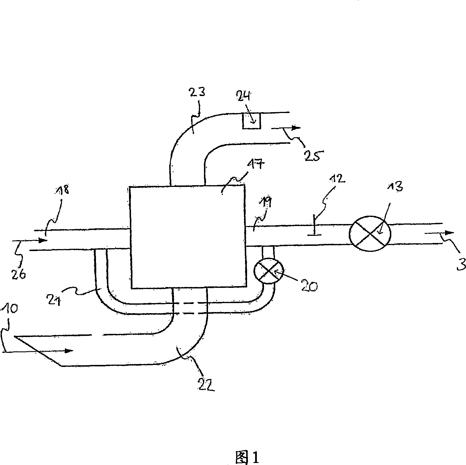
[0031] Figure 1 shows a schematic diagram of an air cooling device. This air cooling device is used in particular to cool the bleed air 26 of the OBIGGS system (not shown in FIG. 1 ). The device mainly comprises a heat exchanger 17 which cools the bleed air 26 supplied to the system.

[0032] Bleed air 26 is provided by the engine or auxiliary power unit (APU). Typically, the temperature of the bleed or supply air 26 is approximately 200 degrees Celsius. To this end, bleed air 26 is fed via inlet line 18 to heat exchanger 17 , cooled and then fed to OBIGGS as air stream 3 via line 19 . The heat exchanger 17 is air-cooled. In this arrangement, air cooling takes place by cooling the air 10 conveyed via the ram air channels 22 and 23 . Furthermore, for ground operations, jet pumps or fans 24 are provided to ensure a corresponding cooling air throughpu...


PUM


Abstract

Nowadays in aircraft so-called on-board inert gas generation systems (OBIGGS) are used to generate inert gases, to which OBIGGS cooled bleed air of engines or auxiliary power units is fed. According to an embodiment of the present invention, an air-cooling device for an OBIGGS system in an aircraft is proposed that comprise a bleed position (1). By way of the bleed position (1), cooling air from an air conditioning unit (4) on board the aircraft can be bled, which cooling air can subsequently be used for cooling supply air (18) for the OBIGGS system. Thus, there is no need for an additionalram-air inlet channel for cooling the supply air. Air resistance and weight are thus reduced, and the stability of the primary structure is enhanced.

Description

[0001] This application claims priority to U.S. Provisional Patent Application No. 60 / 602 444, filed August 16, 2004, and German Patent Application No. 10 2004 039 669.8, filed August 16, 2004, the disclosures of which are It is hereby incorporated by reference. technical field [0002] This application relates to air cooling in aircraft. In particular, the present application relates to a cooling device in an aircraft, a method for cooling air in an aircraft, the use of a corresponding air cooling device in an aircraft, and an aircraft comprising a corresponding air cooling device. Background technique [0003] In aircraft, so-called on-board inert gas generation systems (OBIGGS), ie systems for generating inert gas in aircraft, are used. These OBIGGS systems are used, for example, to generate nitrogen, which is used to displace oxygen from the fuel tank. The cooled bleed air of the engine or auxiliary power unit (APU) is used as the air source for the generation of the i...

Claims


Application Information

Patent Timeline
IPC IPC(8): B64D37/32B64D13/06
CPCY10T137/0391Y02T50/44B64D37/32B64D2013/0677B64D13/06Y02T50/40
Inventor 托马斯·舍雷尔吕迪格·施米特亚历山大·索恩塞夫
Owner AIRBUS OPERATIONS GMBH
Why Eureka
Try Eureka