Friction and wear tester

A friction and wear and experimental machine technology, applied in the field of friction and wear process simulation and detection devices, can solve problems such as errors and incomplete friction and wear measurement, and achieve the effect of solving errors and a high degree of automation

Inactive Publication Date: 2007-08-01
HARBIN INST OF TECH
View PDF0 Cites 44 Cited by
  • Summary
  • Abstract
  • Description
  • Claims
  • Application Information

AI Technical Summary

Problems solved by technology

[0004] The purpose of this invention is to provide a kind of friction and wear testing machine, to overcome the defect that there is a certain error in the traditional friction and wear testing device
The present invention proposes a new idea and device for testing and evaluating friction characteristics, which solves the errors of incomplete measurement of friction and wear in traditional technology

Method used


Image

  • Friction and wear tester
  • Friction and wear tester

Examples


specific Embodiment approach 1

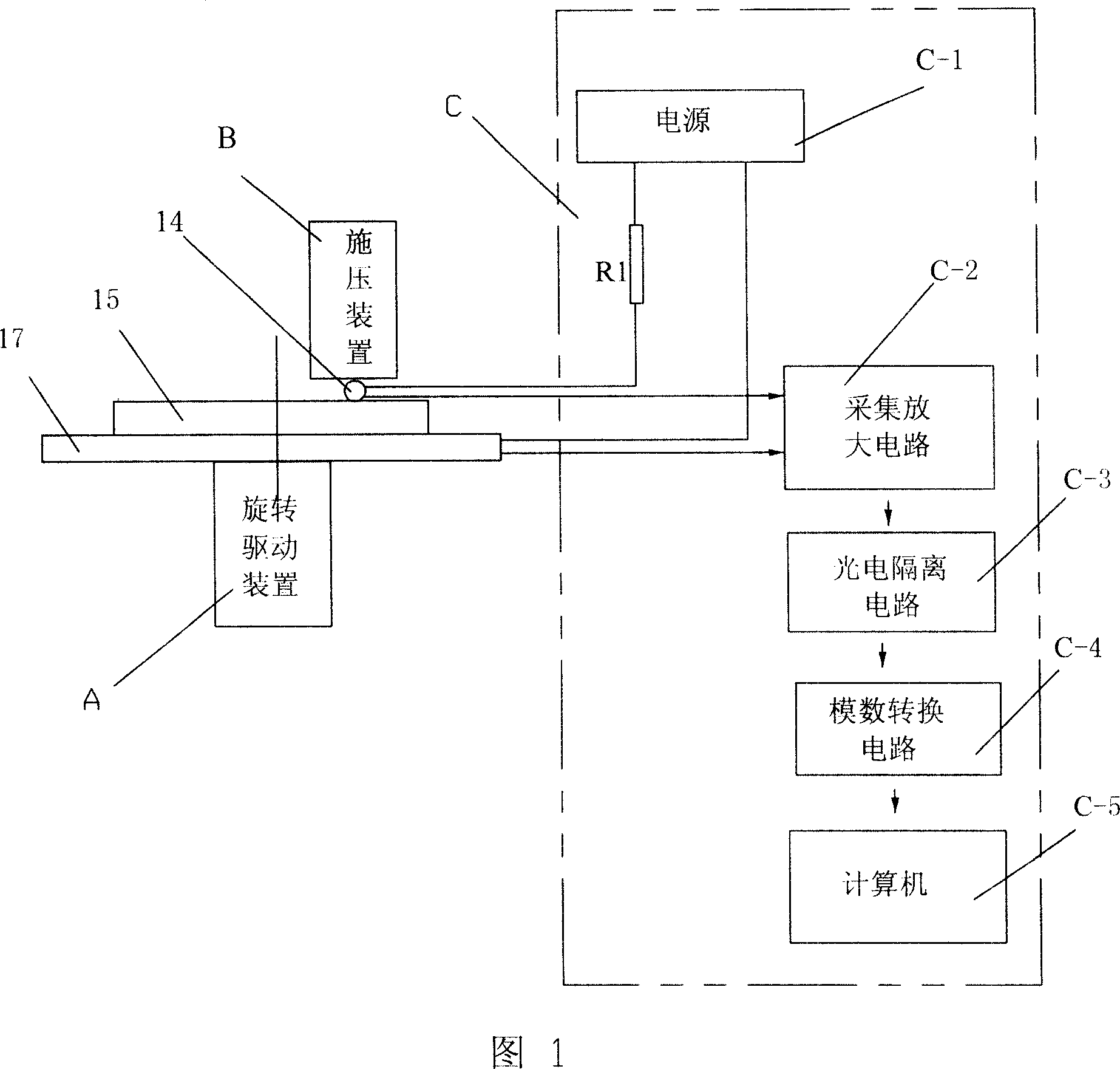
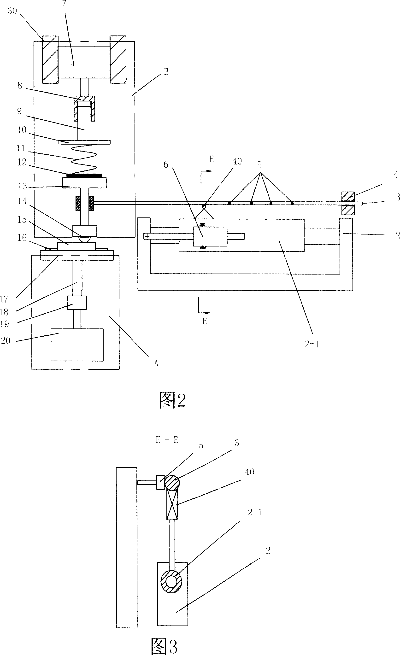
[0007] Specific Embodiment 1: The present embodiment will be specifically described below in conjunction with FIG. 1 , FIG. 2 , and FIG. 3 . This embodiment consists of a turntable 17, a rotary drive device A, a steel ball 14, a pressure device B, a sample resistance detection circuit C, a horizontal guide seat 2, a grating ruler 6, a lever 3, a counterweight 4 and a load cell 5 The sample resistance detection circuit C is composed of a power supply C-1, a resistor R1, an acquisition amplifier circuit C-2, a photoelectric isolation circuit C-3, an analog-to-digital conversion circuit C-4, and a computer C-5. The rotary drive device A It is connected with the lower end surface of the turntable 17 to drive its rotation, the upper end of the steel ball 14 is fixed on the lower end of the pressing device B, the steel ball 14 is arranged above the turntable 17, and one output end of the power supply C-1 is fixed on the On the steel ball 14, the other output end of the power supply ...


PUM


Abstract

This invention relates to one friction loss process analogue and test device, which comprises rotation disc, rotation drive device, steel ball and pressure device and test sample resistance test circuit, wherein, the test resistance value test circuit is composed of power, resistance, sample and amplification circuit, photoelectrical isolation circuit, A/D conversion circuit and computer, wherein, the rotation drive device and rotation disc down end are connected; the steel ball top end is fixed on pressure device with one output end fixed on steel ball with other output end connected to rotation disc; two input ends of collection and amplification circuit are fixed on steel balls and rotation disc.

Description

technical field [0001] The invention relates to an experimental device, in particular to a simulation and detection device of a friction and wear process. Background technique [0002] In the traditional friction and wear test device, the steel ball is fixed as a friction pair, and its positive pressure on the test piece is determined by the loading weight. The specimen rotates at a constant speed with the turntable and makes sliding friction with the steel ball. The friction force is transmitted to the force sensor through the lever, and the computer collects the data of the friction force and draws the friction coefficient-time curve. This evaluation method is the measurement of mechanical parameters such as friction coefficient, wear amount, etc. under uniform sliding friction, but the actual friction and wear are mostly non-uniform speed processes, and uniform speed measurement cannot better represent the actual friction process. The measurement is not comprehensive, a...

Claims


Application Information

Patent Timeline
Patent Type & Authority Applications(China)
IPC IPC(8): G01N3/56G01N19/02
Inventor 田修波刘磊杨士勤
Owner HARBIN INST OF TECH
Why Eureka
Try Eureka