
Tap switching device when loading

A tap switching and tap technology, which can be used in conversion equipment that can be converted to DC without intermediate conversion, protection switch operation/release mechanisms, inductors, etc. , to achieve the effect of suppressing consumption and realizing cut-off capacity

Active Publication Date: 2007-08-01
KK TOSHIBA
View PDF1 Cites 8 Cited by
  • Summary
  • Abstract
  • Description
  • Claims
  • Application Information

AI Technical Summary

Problems solved by technology

Therefore, it can be said that the loss of the main electron tube A is easily significantly increased compared with the resistance tubes C and D.
If the contact state continues to deteriorate, there may be a long-term arc or restriking of the arc
In other words, there is a problem that the electrode contact of the main valve is severely consumed in the tap changer of the prior art under load.

Method used


Image

  • Tap switching device when loading
  • Tap switching device when loading
  • Tap switching device when loading

Examples


no. 2 Embodiment approach

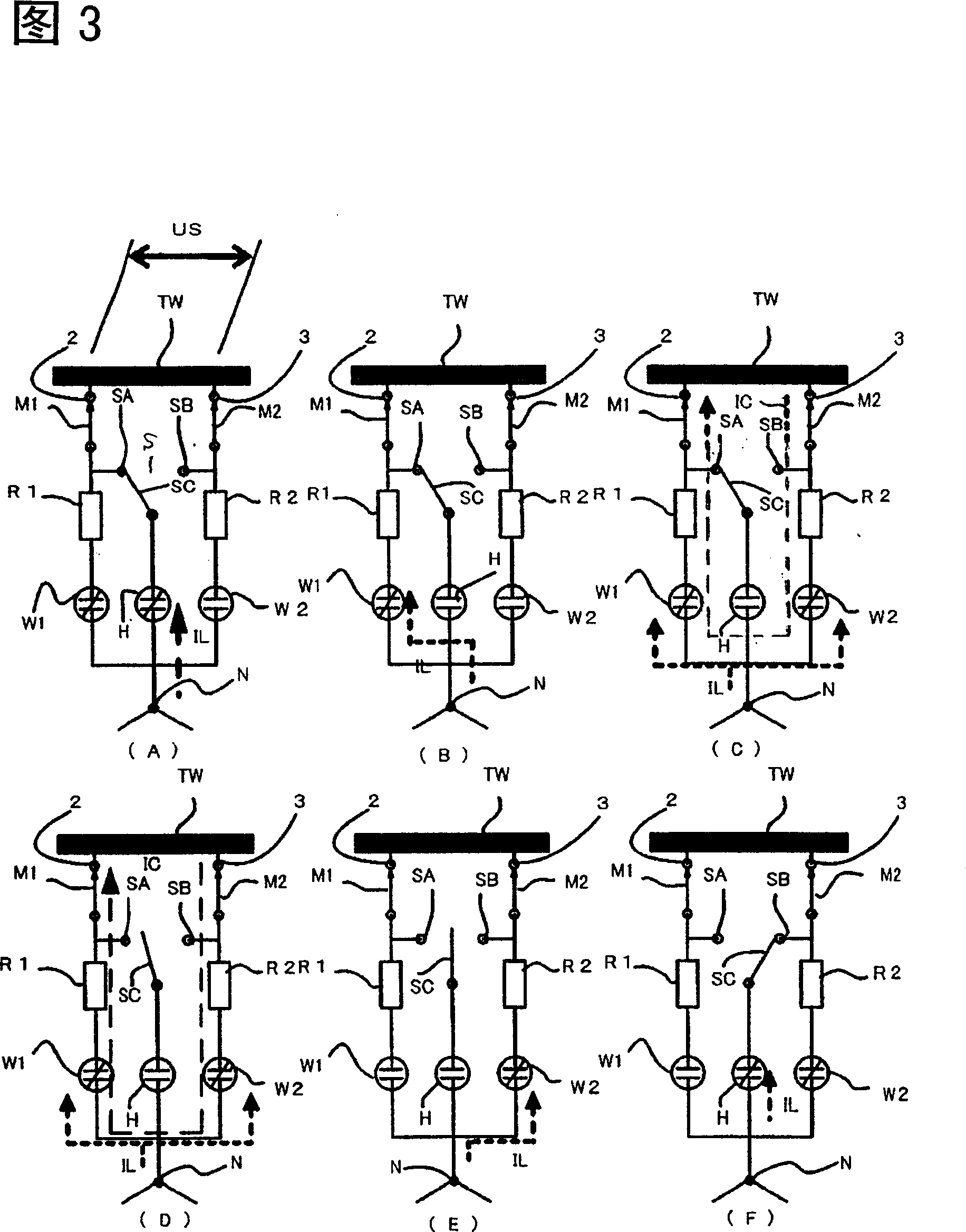
[0071] Next, a second embodiment of the present invention will be described with reference to FIGS. 3 and 4 .

[0072] (2-1) Structure

[0073] The circuit structure of the second embodiment is the same as that of the above-mentioned first embodiment, but the switching procedure is different. The second embodiment is characterized in that the valve W2 for resistors on the tap 3 side that is not energized before the switching operation is contact-closed, and the valve W1 for resistors on the tap 2 side that is energized before the switching operation is contact-opened, and then the main valve H is configured to be switched by contact-closing. program.

[0074] (2-2) Switch program

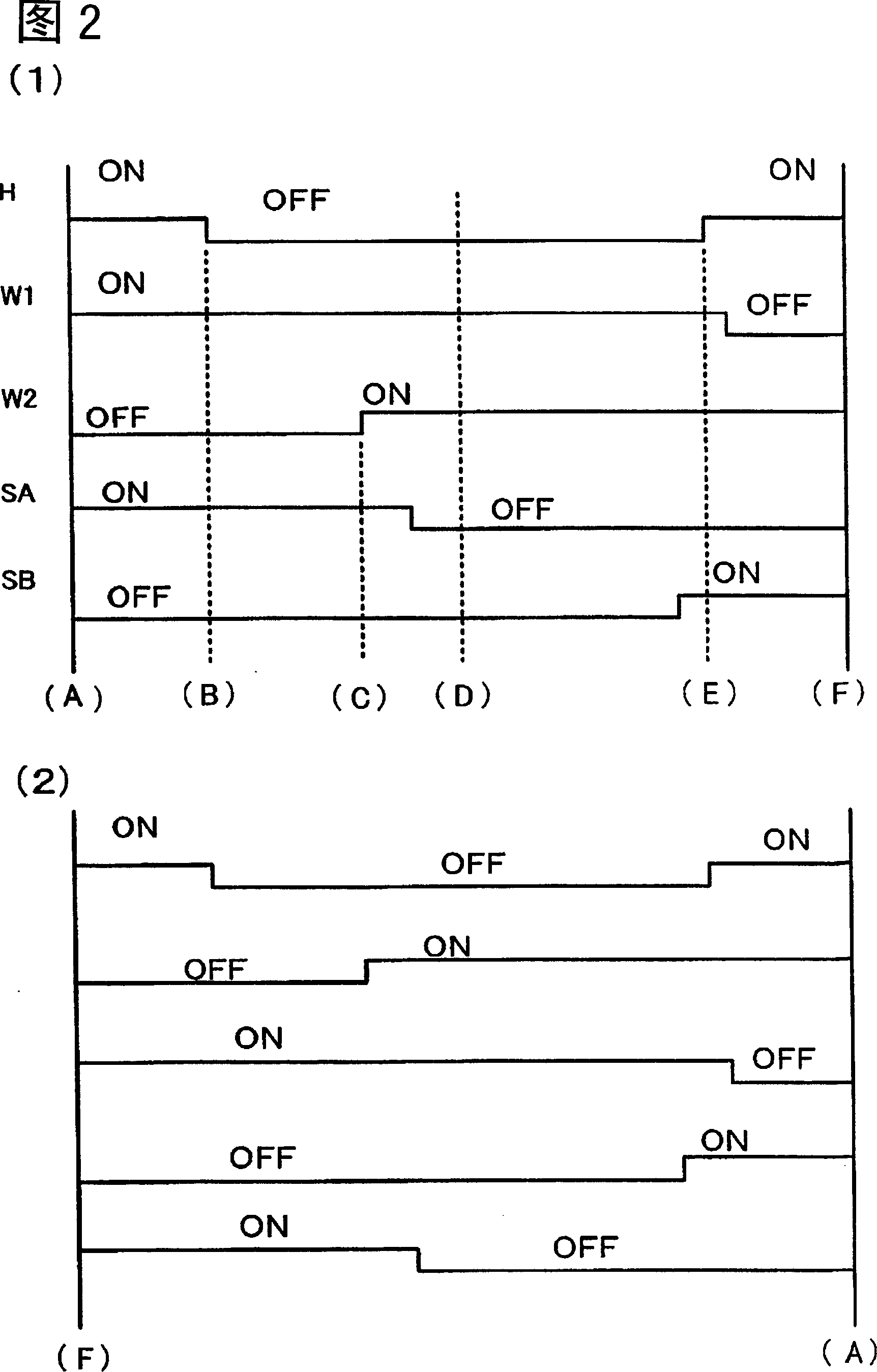
[0075] Hereinafter, the above features will be described in order based on the handover procedure shown in (A) to (F) of FIG. 3 . (A) to (F) of FIG. 3 show the handover process shown in (A) to (F) of FIG. 4( 1 ).

[0076] The switching program of the second embodiment can be said that the flow f...

no. 3 Embodiment approach

[0094] Next, a third embodiment of the present invention will be described with reference to FIGS. 5 and 6 .

[0095] (3-1) Structure

[0096] The circuit structure of the third embodiment is the same as that of the above-mentioned first embodiment, but in the switching program, the switching operation of the diverter switch S is performed before the contact closing operation of the resistor valve W2 on the side of the non-energized tap 3 .

[0097] That is, in the state where the main valve H is open and the resistance valve W1 on the tap 2 side that is energized before the switching operation is in contact closed, and the resistance valve W2 on the tap 3 side that is not energized before the switching operation is in a contact-open state, the switch S can be switched. The movable contact SC starts to act and disconnects the electrical connection with the fixed contact SA that has been in contact before the switching action.

[0098] Then, the resistor on the tap 3 side that...


PUM


Abstract

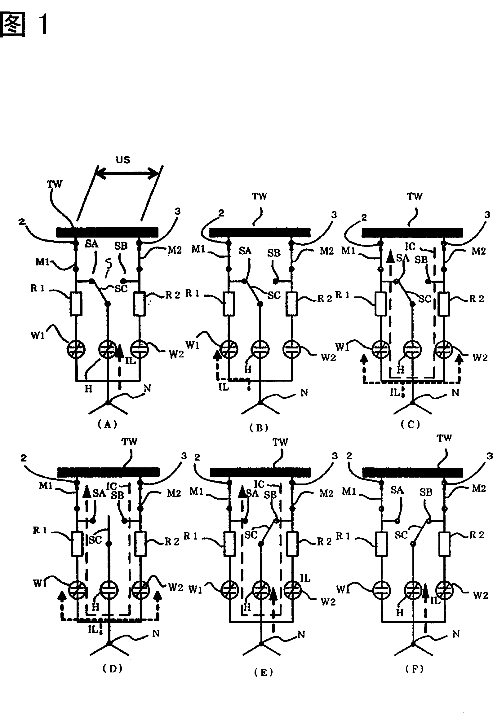
The present invention provides a load-time tap switching device that suppresses consumption of electrode contacts of a main valve by reducing the maximum value of the cut-off current of the main valve that has a large number of cut-off times, and realizes stabilization of cut-off capability. It adopts the structure that the contact of the resistance valve (W1) on the tap side that is energized before the switching operation is closed, and the main valve (H) is opened when the contact of the resistance valve (W2) on the tap side that is not energized before the switching operation is opened.

Description

technical field [0001] The present invention relates to a dual-resistor and three-electron-tube tap switching device under load, in particular to a tap switching device under load which reduces the cut-off current of a main electron tube composed of vacuum electron tubes and thereby suppresses the loss of electrode contacts of the vacuum tubes. Background technique [0002] In order to adjust the voltage of the power transmission system to make it stable, a tap switching device is generally used in the transformer connected to the power transmission system when there is load. The tap switching device during load includes a switching switch and a tap selector, but the switching switch generally uses a vacuum tube composed of a pair of electrodes that can be separated or contacted in a vacuum container as the cut-off element. It has been proposed that each phase has 2 A current-limiting resistor and a dual-resistance three-tube switching switch (refer to Patent Document 1) sch...

Claims


Application Information

Patent Timeline
Patent Type & Authority Applications(China)
IPC IPC(8): H01F29/04
CPCH01H9/0038H01F29/04H01H71/10H02J3/04H02M5/12
Inventor 泷口幸延
Owner KK TOSHIBA
Learn More