Method and measuring arrangement for nondestructive analysis of an examination object by means of X-radiation

A measurement device, X-ray technology, applied in the direction of measurement devices, radiation measurement, X-ray equipment, etc., can solve the problems of no optical system, low depth of 3D analysis information, etc., and achieve the effect of optimizing the structure

Inactive Publication Date: 2007-08-08
SIEMENS AG
View PDF0 Cites 16 Cited by
  • Summary
  • Abstract
  • Description
  • Claims
  • Application Information

AI Technical Summary

Problems solved by technology

[0007] But in most cases, true 3D analysis is hampered by the fact that either the information depth is too low or no corresponding optics are available for imaging element-specific signals

Method used


Image

  • Method and measuring arrangement for nondestructive analysis of an examination object by means of X-radiation
  • Method and measuring arrangement for nondestructive analysis of an examination object by means of X-radiation

Examples


Embodiment Construction

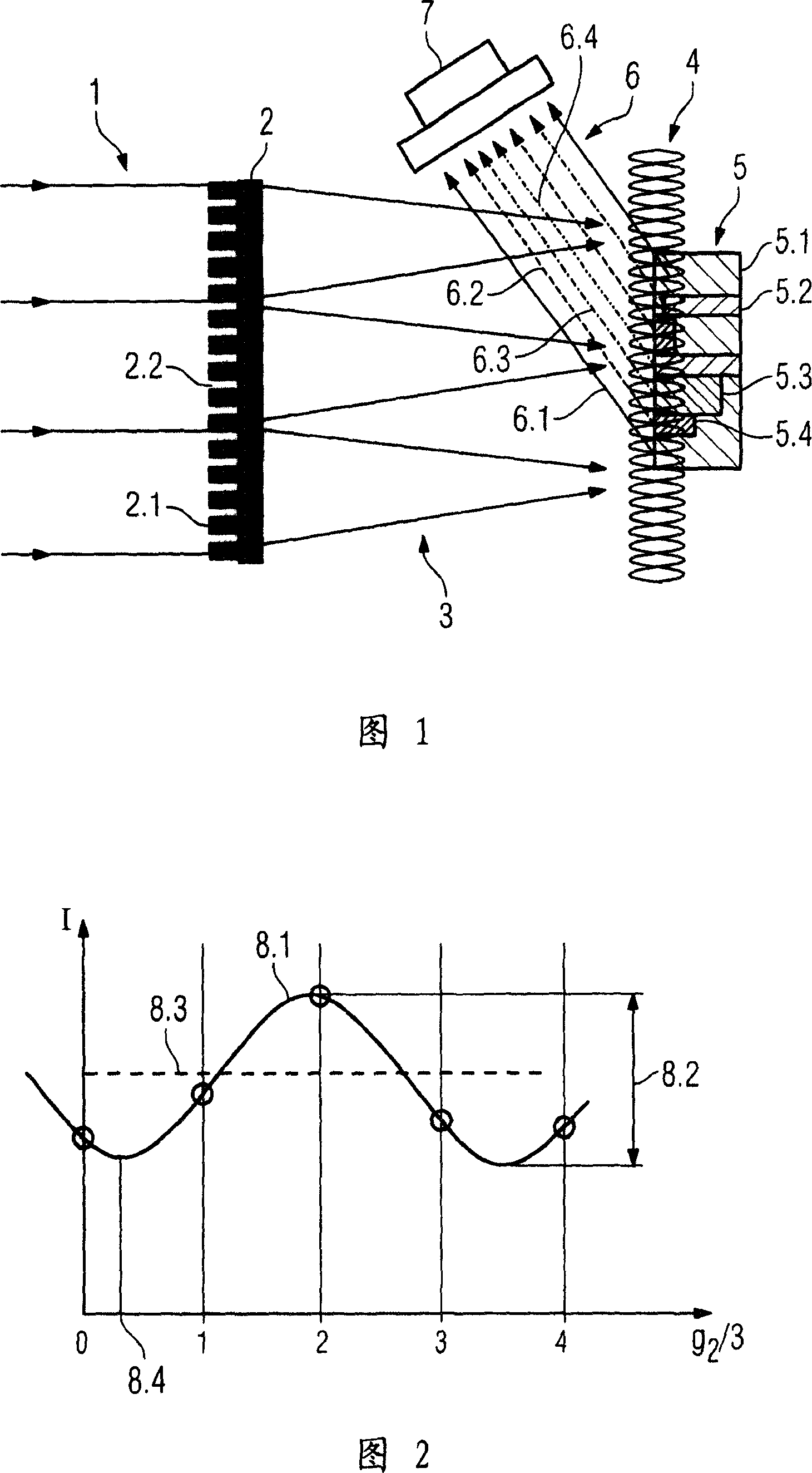
[0097] FIG. 1 shows a measuring device according to the invention, consisting of an absorption or phase grating 2 with grid bars 2.1 and gaps 2.2, which forms a standing wave field 4 of penetrable X-rays, wherein the standing wave field 4 is positioned Radiation, preferably fluorescent radiation 6 , is generated within the body of the examination subject 5 and in this examination subject 5 as a function of the elemental distribution measured by the detector 7 .

[0098] In the diagram shown in FIG. 1 , starting from the left, i.e. from an x-ray source not shown here, coherent or quasi-coherent x-rays 1 fall on an x-ray grating 2 in which diffracted x-rays are generated 3 and thereby generate a standing wave field 4 whose planar extension is substantially equal to the planar extension of the absorbing or phase grating 2 generating the standing wave field. In the figure shown, examination objects 5 with different substances 5.1 to 5.4 are arranged in this standing wave field 4 ....


PUM


Abstract

A method and a measuring arrangement are disclosed for nondestructive analysis of an examination object. In at least one embodiment of the method, x-radiation having a specific energy spectrum is generated by an x-ray source, with the aid of at least one x-ray / optical grating in the beam path of the x-radiation there is generated a standing wave field of this x-radiation that is positioned at least partially in the examination object, and the radiation excited by the x-ray standing wave field in the examination object is measured as a function of at least one relative position between the examination object and the x-ray standing wave field. Further, a material distribution in the examination object is inferred from the measurement result of the radiation excited by the x-ray standing wave field.

Description

technical field [0001] The invention relates to a method and a measuring device for the non-destructive analysis of an examination object by means of x-rays, wherein the examination object is irradiated with x-rays and the radiation emitted by the object is thereby measured outside the radiation path of the incident radiation. Background technique [0002] In X-ray radiology and X-ray tomography it is known to determine the absorption coefficient μ(x,y,z) of an object with precise spatial resolution and to generate an image of the object on the basis of this information. This imaging technique is based on so-called absorption contrast, which is widely used in medical diagnostics and non-destructive inspection in industry. In this absorption contrast imaging, the different object regions are weighted according to their mass absorption coefficients. By finding the value of the local absorption coefficient μ(x, y, z), a rough classification of the element concentration or tiss...

Claims


Application Information

Patent Timeline
Patent Type & Authority Applications(China)
IPC IPC(8): A61B6/00G01N23/04G01N23/20G01N23/06H05G1/02H05G1/62G01T1/28G01T7/00G21K1/06G21K1/02
CPCA61B6/484A61B6/4291G01N2223/419G01N2223/612
Inventor 乔基姆・鲍曼马丁・恩格尔哈特乔格・弗罗伊登伯格尔埃克哈德・亨普尔马丁・霍海泽尔托马斯・默特尔迈耶斯蒂芬・波佩斯库曼弗雷德・舒斯特
Owner SIEMENS AG
Why Eureka
Try Eureka