Wire-clamping device for sewing machine

A sewing machine and thread clamping technology, applied in the direction of sewing machine components, tension devices, sewing equipment, etc., can solve the problems of driver thrust lag, reduce friction, reduce friction, etc., achieve high-speed response, maintain reproducibility, and eliminate starting The effect of time delay

Active Publication Date: 2012-02-22
JUKI CORP
View PDF4 Cites 0 Cited by
  • Summary
  • Abstract
  • Description
  • Claims
  • Application Information

AI Technical Summary

Problems solved by technology

[0015] However, in the existing thread clamping device, since the bearing structure of the direct-acting driver is composed of sliding bearings, under the action of the friction force caused by the weight of the movable parts of the driver and the friction coefficient of the bearing, the thrust of the driver will be generated. Hysteresis characteristic, there is a difference in thread tension value when the thrust is increased or decreased
[0016] In addition, the friction coefficient varies due to the processing accuracy, wear, or temperature of the parts of the bearing, and as a result, the hysteresis characteristic also varies, and the thread tension varies, resulting in a decrease in reproducibility.
[0017] In addition, as the tension setting is reduced, the influence of the above-mentioned frictional force becomes larger, so the thread tension of the set value cannot be obtained, and the reproducibility of the variation is also low, so it is impossible to achieve a low tension of the thread tension.
[0018] In addition, since the wire tension is the value obtained by subtracting the friction force (mainly static friction force) from the thrust force of the driver, it takes a certain amount of time until the wire tension is generated even if a driving current is passed through the driver in a conventional structure with a large friction force. , does not improve responsiveness
[0019] In addition, according to the hysteresis characteristic depending on the friction force of the bearing, there is a difference in the thread tension value due to the increase or decrease of the thrust force. Therefore, when reducing the thread tension, temporarily reduce the drive current to a value lower than the set value and then increase it to the set value. value, when such countermeasures are taken, although the difference in thread tension becomes smaller, it is impossible to achieve variable control of high-speed thread tension because the variable sequence of the drive current takes extra time.
[0020] In addition, in order to reduce the mass of the movable part in order to reduce the friction force, the mass of the movable part cannot be greatly reduced by balancing with the thrust force of the actuator, so there is a limit to reducing the friction force
[0021] In addition, due to the wear caused by friction, it is difficult to maintain the same quality state for a long time because there is a difference from the friction state at the beginning of shipment.
In order to avoid quality changes, there is a problem that maintenance such as replacement of bearing parts is required

Method used


Image

  • Wire-clamping device for sewing machine
  • Wire-clamping device for sewing machine
  • Wire-clamping device for sewing machine

Examples


Embodiment Construction

[0084] Hereinafter, the best mode of the thread tension device of the sewing machine will be described in detail with reference to the drawings.

[0085]

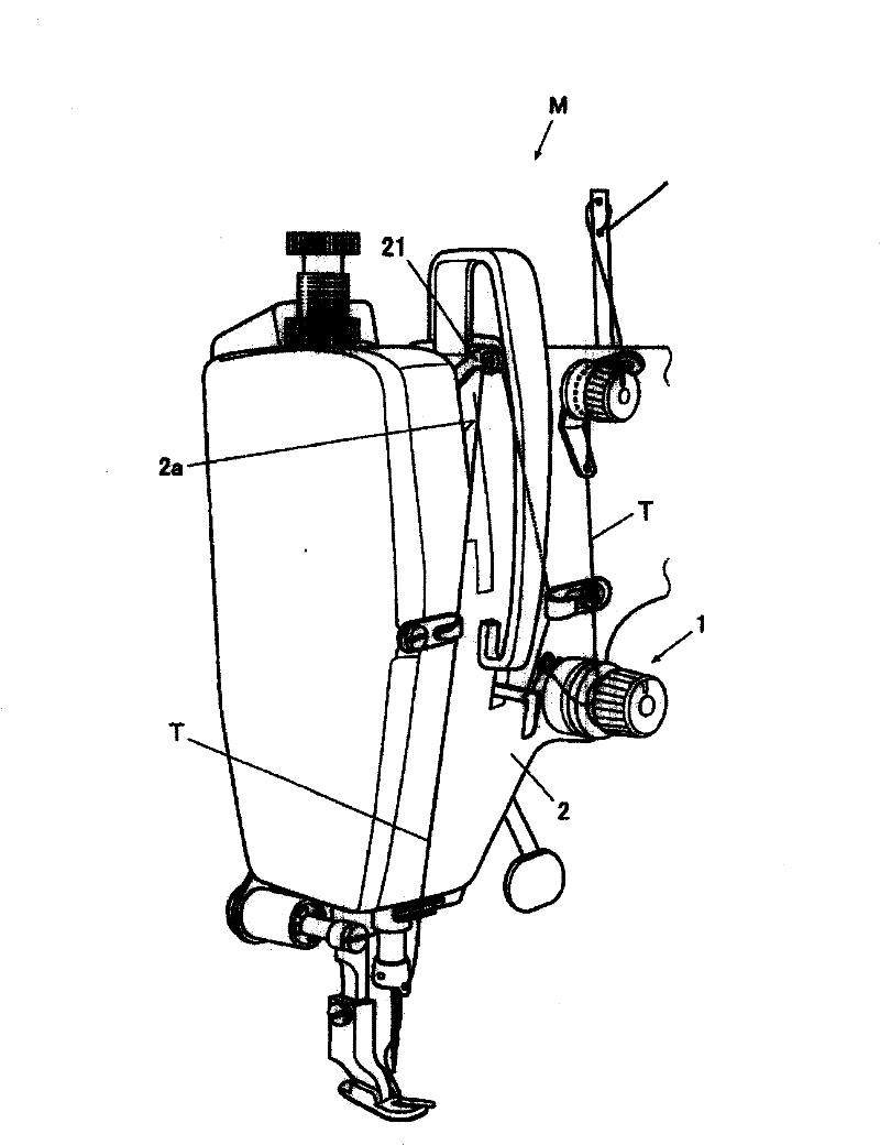
[0086] Such as figure 1 As shown, the thread clamping device 1 is installed near the jaw of the sewing machine head frame 2 of the sewing machine M from the front to the back. Appropriate tension is applied and clamped, and guided to the thread take-up 21. The thread take-up 21 moves along with the rotation of the main shaft (not shown) connected to the sewing machine motor (not shown), and moves up and down along the groove 2a formed in the sewing machine head frame 2, thereby tightening the thread through the Thread T of the sewn thing.

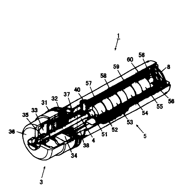
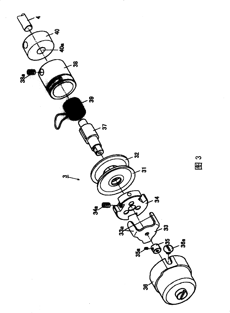
[0087] Such as figure 2 As shown, the thread clamping device 1 has: a thread clamp 3 for applying tension to the thread, a drive disc presser foot 33 so that one side of the clamp disc 31 is close to the other side of the clamp disc 32 as a drive lever 4 as a driving mechanism, a...


PUM


Abstract

A thread tightening device for sewing machine can reduce the friction when driving a drive, and can further improve the reproduce property, response property and durability. The thread tightening device (1) for sewing machine (M) has a pair of tightening disks (31, 32) which holds a thread; a drive mechanism (4, 33) for driving one tightening disk (31) contact to another tightening disk (32) and separate from it; a drive source (5) for driving the drive mechanism (4, 33), the drive source (5) has a movable member (6) which has a movable member shaft (51) moving along the axial direction and permanent magnets (52-55) disposed on the movable member shaft (51); a fixed member (7) which has windings (57-60) wrapped around the permanent magnets (52-55) with a pre-determined distance; and bearings (40, 8) which supports the two end parts of the movable member shaft (51), wherein the bearings at the end parts of the drive source (5) side for supporting the movable member shaft (51) are a plate spring bearings made of plate spring.

Description

technical field [0001] The invention relates to a thread clamping device of a sewing machine capable of automatically changing thread tension. Background technique [0002] Hitherto, as a tension device that can adjust the tension applied to the wire by the tension disc through a driving component such as a voice coil motor, for example, as described in Patent Document 1, it is known to have the following: Figure 20 , Figure 21 The clamping device of the structure shown. [0003] Figure 20 The existing clamping device 110 shown has: voice coil motor 111, movable clamping disc 112 (hereinafter referred to as movable disc 112), fixed clamping disc 113 (hereinafter referred to as fixed disc 113) And drive rod 114 etc. The drive rod 114 is slidably inserted through the opening 112a of the fixed plate 112, and the end 114a on one side is connected to the coil head (coil head) 115 as the movable part of the voice coil motor 111, and the end on the other side 114b abuts again...

Claims


Application Information

Patent Timeline
Patent Type & Authority Patents(China)
IPC IPC(8): D05B47/04H01F7/00
CPCD05B47/04A01K91/18
Inventor 风晴广行
Owner JUKI CORP
Why Eureka
Try Eureka