Temperature controlling method for hot blast drying device used in warp sizing device

A temperature control method and warp sizing technology, which are applied in the direction of temperature control, progressive dryer, non-electric variable control, etc., can solve the problem of large power consumption of electric heaters

Inactive Publication Date: 2007-08-08
TSUDAKOMA KOGYO KK
View PDF2 Cites 13 Cited by
  • Summary
  • Abstract
  • Description
  • Claims
  • Application Information

AI Technical Summary

Problems solved by technology

However, since it is a technology that often uses electric

Method used


Image

  • Temperature controlling method for hot blast drying device used in warp sizing device
  • Temperature controlling method for hot blast drying device used in warp sizing device
  • Temperature controlling method for hot blast drying device used in warp sizing device

Examples


Embodiment Construction

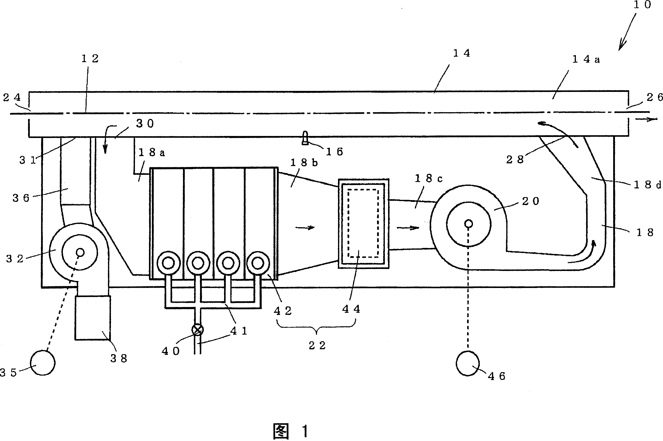
[0029] A specific mode for implementing the present invention will be described below using the drawings. Referring to Fig. 1, the hot air drying device 10 used in the warp yarn sizing device makes the sheet-like warp yarn 12 in the wet state 12 that is sized in the previous process (not shown) pass through the inside of the drying chamber 14 that sends hot air to dry. , In the subsequent post-process, the warp yarns are further dried by contacting and passing through an air cylinder dryer (not shown), and wound into warp yarn bundles (not shown).

[0030] In general, the hot air drying device 10 has a box-shaped drying chamber 14 and an air heater 22, and the air heater 22 is arranged on the entire air supply path 18 passing through the inside of the drying chamber 14. The air blower 20 heats the air supplied to the drying chamber 14, and is comprised by the some heater arrange|positioned.

[0031] The drying chamber 14 extends along the warp traveling direction, has an air ...


PUM


Abstract

The object of the present invention is to provide a temperature control technology which is used in a warp yarn sizing apparatus and for hot air drying apparatus having several air heaters with different kinds and can improve the productivity of good warp yarn bundle and is in favor of the energy cost. A temperature controller of the invention at least programs a first control mode which detects the inner temperature of a dry chamber, outputs a heat operating signal to each heat regulator to make the detected temperature adjacent to a prescribed value to execute temperature control; and a second control mode for outputting a heat operating signal for restraining the heating unit function extend in the heat compared with the first control mode, the temperature controller is running in the hot air drying apparatus to execute one of the two control modes, and execute another control mode when the internal temperature of the dry chamber becomes prescribed status.

Description

technical field [0001] The present invention relates to a technology of a hot air drying device used in a warp sizing device, and more specifically, relates to a technology capable of suppressing energy costs in a hot air drying device having a plurality of air heaters of different types. Background technique [0002] The hot air drying device used in the warp sizing device generally has: a drying chamber with a circulation path of airflow along the warp yarn running path in a wet state of sizing; An air heater configured to heat the air entering the drying chamber. Such air heaters include steam radiators that heat air by supplying steam (for example, see Patent Document 1) and electric heaters that use electric energy to heat air (for example, see Patent Document 2). [0003] There are advantages and disadvantages of each of the air heaters mentioned above. The air heater composed exclusively of steam radiators as in Patent Document 1 uses steam as a heat source, so it t...

Claims


Application Information

Patent Timeline
IPC IPC(8): D06B15/09F26B13/00D06B23/00D06M15/11F24H3/00G05D23/00
Inventor 山本刚
Owner TSUDAKOMA KOGYO KK
Why Eureka
Try Eureka