Artificial intervertebral disk insertion jig, jig set, and artificial intervertebral disk

A technology of intervertebral discs and fixtures, applied in spinal implants, medical science, prostheses, etc., can solve the problem of incomplete integration of bone fiber replacement liners and vertebral bodies with artificial intervertebral discs, artificial intervertebral discs inserted between vertebral bodies, deformation, etc. question

Inactive Publication Date: 2007-08-08
TAKIRON CO LTD
View PDF3 Cites 6 Cited by
  • Summary
  • Abstract
  • Description
  • Claims
  • Application Information

AI Technical Summary

Problems solved by technology

However, there is a concern that as bone fibers invade and grow within the liner, it could deform due to weight
There is a possibility here that the fusion between the liner and the vertebral body and the artificial disc may become incomplete due to the bone fiber replacement liner, resulting in a weakened force that binds / fixes the upper and lower vertebral bodies
In addition, the liner consists of a porous substance, is fragile, and therefore there is also the possibility that the liner edge wears away producing fine particles
In addition, since the core material of the artificial intervertebral disc is a three-dimensional fibrous structure, the technique of forming a screw hole therein and screwing the front end of the rod-shaped insertion jig into the hole axis prepared before insertion, as in the case of the cage in Patent Document 1, cannot be used. for inserting an artificial disc between the vertebral bodies

Method used


Image

  • Artificial intervertebral disk insertion jig, jig set, and artificial intervertebral disk
  • Artificial intervertebral disk insertion jig, jig set, and artificial intervertebral disk
  • Artificial intervertebral disk insertion jig, jig set, and artificial intervertebral disk

Examples


Embodiment Construction

[0096] Embodiments of the present invention will be described in detail with reference to the accompanying drawings.

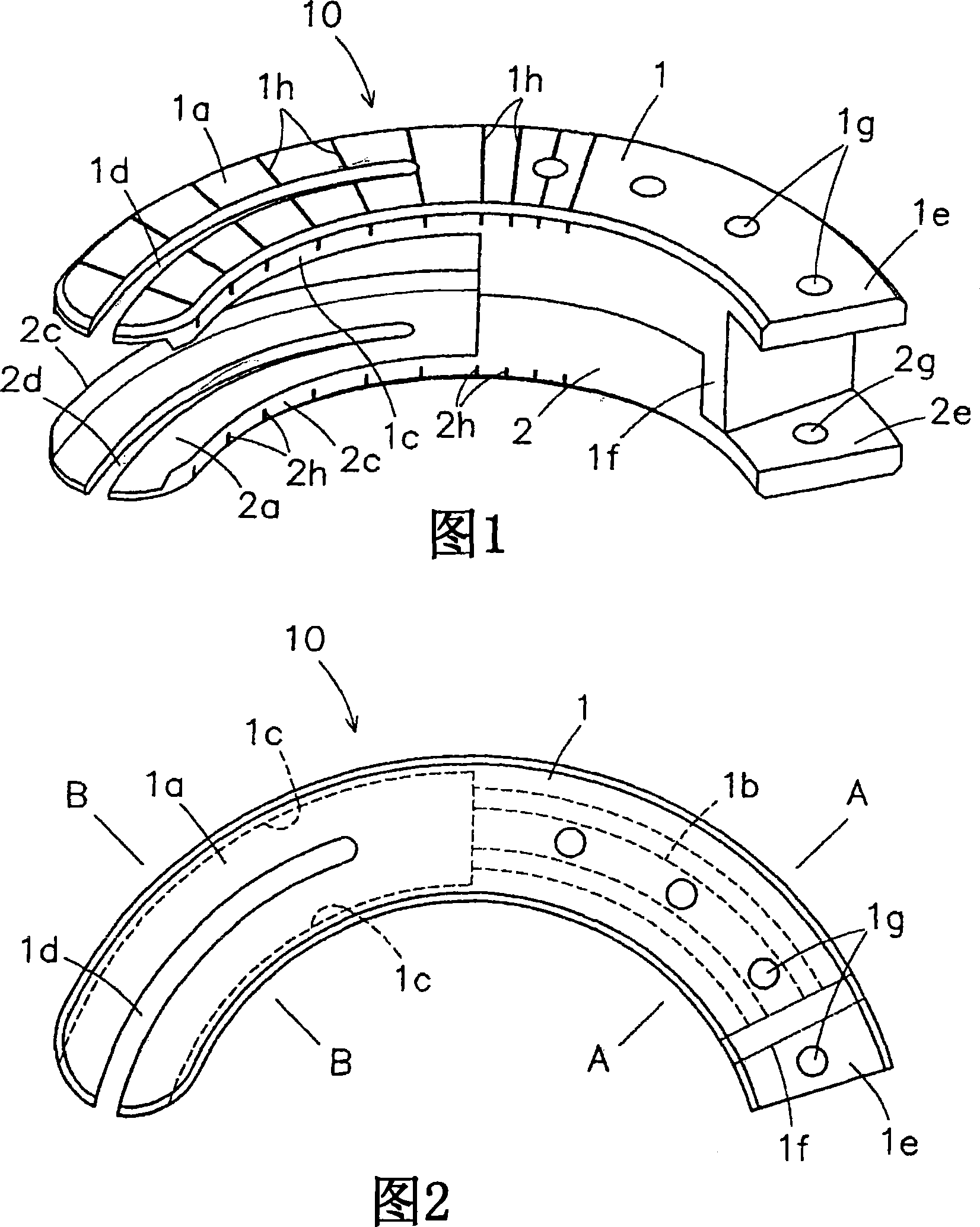
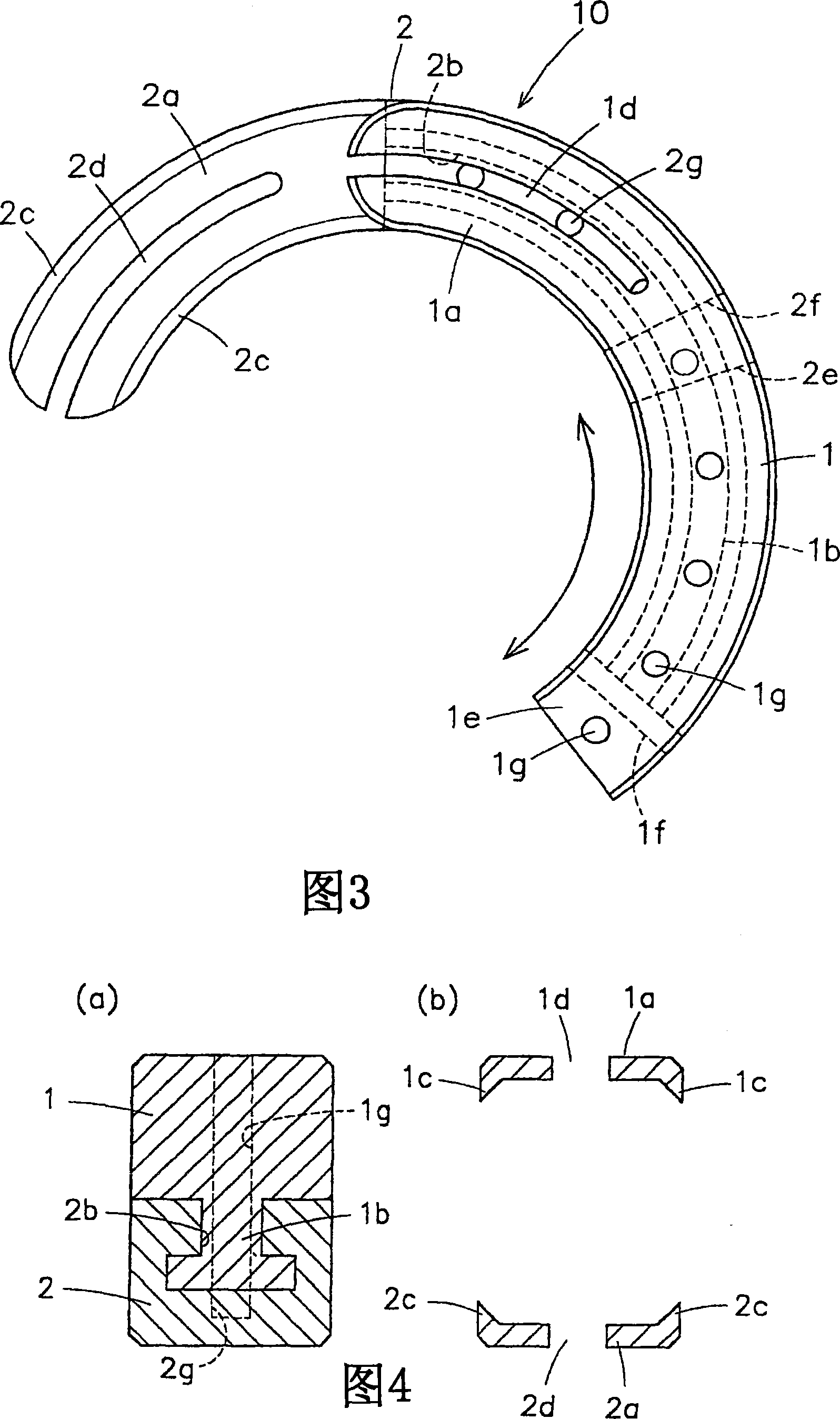
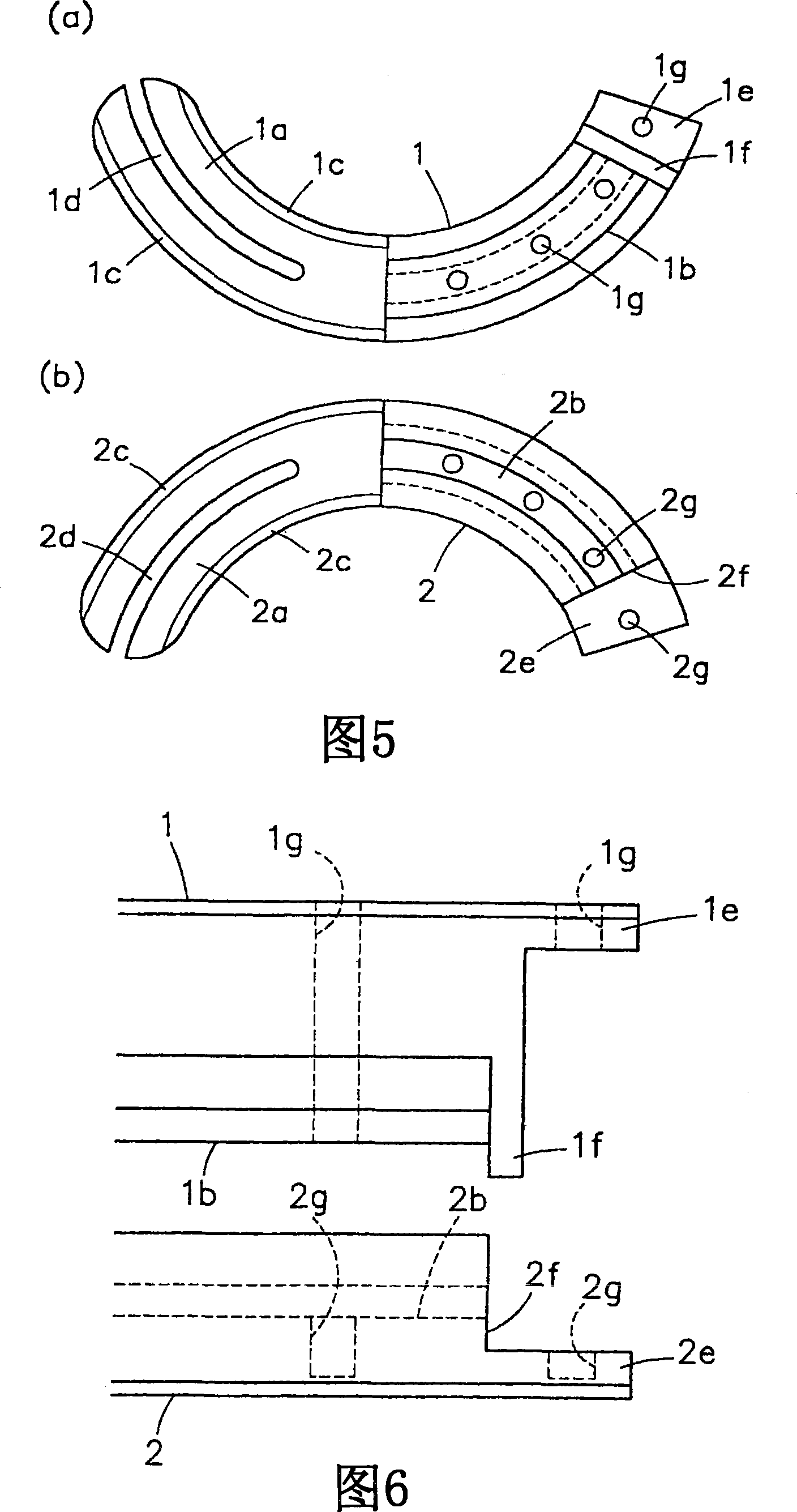
[0097] The first artificial intervertebral disc insertion jig 10 illustrated in FIGS. 1 to 6 includes a pair of jigs, namely, an upper jig 1 and a lower jig 2 , which are arc-shaped curved jigs having the same radius of curvature. The upper jig 1 and the lower jig 2 have an upper holding part 1a and a lower holding part 2a formed as front parts thereof, each of which is tongue-shaped and serves to hold the arc-shaped artificial intervertebral disc 3 shown in FIG. 7 .

[0098] As shown in Fig. 4(a) and Fig. 5(a), the rear portion of the upper jig 1 (the rear portion on the rear side of the upper holding member 1a) has a ridge portion 1b having an inverted T-shape in cross section on the lower side thereof and Bend along the center line of the upper fixture 1 (not shown in the figure). The rear portion of the lower jig 2 (the rear portion on the rear side of th...


PUM

PropertyMeasurementUnit
widthaaaaaaaaaa
diameteraaaaaaaaaa
diameteraaaaaaaaaa

Abstract

A self-sustained artificial intervertebral disk that has flexible nearly ideal mechanical transformation characteristics and durability, exhibiting high vertebra bonding fixing force; and an artificial intervertebral disk insertion jig capable of easily and securely inserting and setting this artificial intervertebral disk between adjoining vertebrae. There is provided an artificial intervertebral disk comprising a core material constituted of a texture structure obtained by forming an organic fiber into a triaxial or further multiaxial three-dimensional woven texture, or knitted texture, or composite texture thereof and, superimposed on both upper and lower surfaces of the core material, plates of a polymer capable of being in vivo decomposed and absorbed which contains a bioactive bioceramic powder. Preferably, the superimposed plates are those having a multiplicity of holes made therethrough, the through-holes optionally packed with a material capable of being in vivo decomposed rapidly and absorbed, the material exhibiting bone conduction and / or bone induction properties. Further, there is provided an insertion jig comprising a combination of upper jig and lower jig fitted together so as to be capable of avoiding detachment in the vertical direction and capable of sliding back and forth, and further comprising an upper holding part and lower holding part for holding the artificial intervertebral disk, respectively disposed in front parts of the upper jig and lower jig.

Description

technical field [0001] The present invention relates to a self-contained, biomimetic artificial intervertebral disc having a configuration comprising a fibrous structure comprising a three-dimensional braided material such as a core material; an artificial intervertebral disc insertion jig for easily inserting the artificial intervertebral disc between adjacent vertebral bodies, and fix them in correct positions; and a jig device, which includes an artificial intervertebral disc insertion jig and an insertion guide jig. Background technique [0002] Various artificial intervertebral discs have been developed. Among the useful artificial discs are the artificial discs of sandwich construction, which consist of upper and lower metal plates, which are made of, for example, Nitinol alloy, and arranged in the middle of the plates are spheres of ultra-high molecular polymer, which act as ball bearings and give the disc required mobility. Although the mobility of the artificial i...

Claims


Application Information

Patent Timeline
Patent Type & Authority Applications(China)
IPC IPC(8): A61B17/56A61B17/58A61F2/44A61L27/00
CPCA61F2220/0025A61F2002/4627A61F2002/30594A61F2/442A61F2002/30062A61F2002/30563A61F2002/30471A61L27/00A61F2002/30841A61F2002/30133A61F2002/30461A61F2250/0097A61F2230/0015A61F2250/0068A61F2310/00179A61F2220/0075A61F2002/30131A61F2002/30387A61F2002/448A61F2002/30617A61F2220/0091A61F2/4611A61F2002/30795A61F2002/3068A61F2210/0004A61F2002/304A61F2230/0013A61F2002/30785A61F2002/4495A61B17/58A61B17/56A61F2/44
Inventor 敷波保夫茑薰川边康弘
Owner TAKIRON CO LTD
Why Eureka
Try Eureka