Permanent magnet suspension bearing used in turbine

A magnetic levitation bearing and turbine technology, applied in the mechanical field, can solve the problems of high cost, insufficient supporting force, and inability to effectively support the rotor

Inactive Publication Date: 2007-08-15
JIANGSU UNIV
View PDF1 Cites 8 Cited by
  • Summary
  • Abstract
  • Description
  • Claims
  • Application Information

AI Technical Summary

Problems solved by technology

Its advantage is that there is no loss of mechanical bearings, but its complex structure and high cost are not widely used
The inventor once developed a permanent magnetic suspension bearing and obtained a patent (96

Method used


Image

  • Permanent magnet suspension bearing used in turbine

Examples


Embodiment Construction

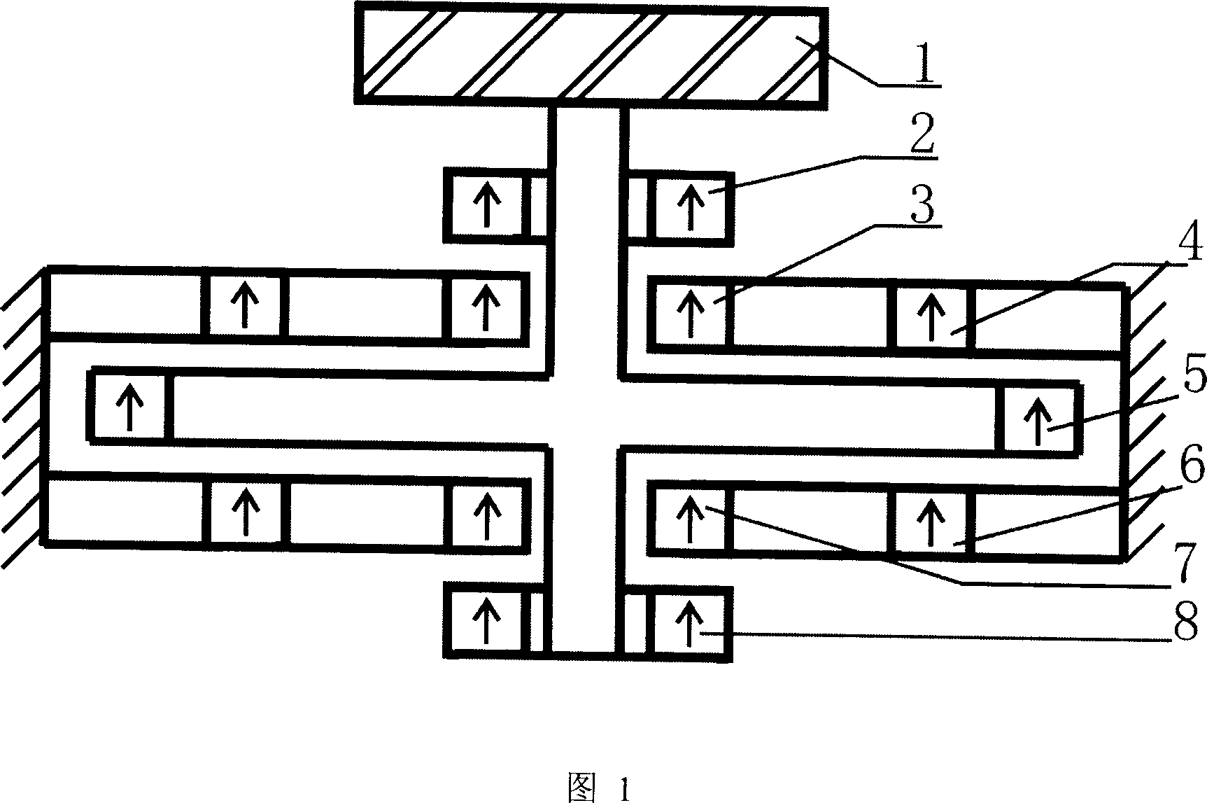
[0009] Now in conjunction with Fig. 1, the structure and working principle of the permanent magnetic suspension bearing applied to the turbine will be described in detail.

[0010] As shown in Figure 1: the turbine blade 1 is installed at the end of the rotor; the annular permanent magnets 2, 5 and 8 are installed on the rotor, and the annular permanent magnets 3, 4 and 6, 7 are installed on the stator. Ring-shaped permanent magnets 2, 3 and 7, 8 are equal in size and arranged coaxially and in the same direction. The mutual attraction between them acts as a radial bearing, because any disturbance in the horizontal direction, whether it is parallel to the paper surface Or perpendicular to the paper, it will be hindered by the ring permanent magnets 2 and 3 or the ring permanent magnets 7 and 8; in other words, the horizontal translation of the rotor will be hindered by the ring permanent magnets 2 and 3 And the obstacle of attraction between 7 and 8. For the rotation of the ro...


PUM


Abstract

The invention relates to a permanent magnetic suspending bearing used as high-speed long-time continuous-rotation turbine mechanics. The turbine blades (1) are mounted on the end of a rotor, annular permanent magnetic steels (2, 5, 8) are mounted on the rotor, annular permanent magnetic steels (3, 4, 6, 7) are mounted on a stator, the annular permanent magnetic steels (2, 3) are in same size as the annular permanent magnetic steels (7, 8) while they are coaxially arranged in same direction with adsorption between and radial bearing function, the annular permanent magnetic steels (4, 5, 6) are different in size, but coaxially arranged in same direction with counter force to confirm the axial balance and stability of rotor. When rotation speed reaches preset value, the rotation inertia of rotor can confirm the rotor stably rotates. The invention has the advantages in non mechanical contact between the rotor and the stator, non mechanical abrasion, and continuous service.

Description

technical field [0001] The invention relates to the mechanical field, in particular to a permanent magnetic suspension bearing used as a high-speed, long-term and continuous-running turbine (turbine). Background technique [0002] At present, the bearings of rotating machinery include mechanical bearings, hydraulic bearings, air bearings, etc., and the service life of them is limited due to mechanical wear or mechanical failure of the bearings. Magnetic pumps have been intensively studied in the past few decades. The first magnetic pump test model was successfully developed by Bramm in the early 1980s (Bramm G, Novak P and Olsen DB: A free-floating body as the motor of a centrifugal blood pump for LVADor TAH.Euro.Soc. Artif. Organs Proc., 8, 41-45, 1981). The first applied magnetic pump was developed by Dr. Akamatzu et al. It uses a hybrid bearing system of electromagnetic bearing (EMB) and permanent magnetic bearing (PMB) (Akamazu T: Centrifugal blood pump with a magnetic...

Claims


Application Information

Patent Timeline
IPC IPC(8): F01D25/16F16C32/04
Inventor 钱坤喜
Owner JIANGSU UNIV
Why Eureka
Try Eureka