Monocase battery voltage balance method and balancer in the charging/discharging process of the dynamic battery group

A power battery pack, charging and discharging process technology, applied to battery circuit devices, current collectors, electric vehicles, etc., can solve problems such as permanent battery damage, low terminal voltage, and unbalanced discharge of single cells

Inactive Publication Date: 2007-08-15
HARBIN INST OF TECH
View PDF0 Cites 18 Cited by
  • Summary
  • Abstract
  • Description
  • Claims
  • Application Information

AI Technical Summary

Problems solved by technology

The power battery pack is generally composed of multiple single cells connected in series. After multiple single cells are connected in series, due to the difference in the chemical properties of the single cells, there will often be unbalanced discharge of each single cell during use. The specific performance (1) When discharging, the energy of some single cells will be lower than that of other single cells, which means that its terminal voltage is lower than that of other single cells. When the voltage has not dropped to the protection voltage, the voltage of these single cells with low terminal voltage has dropped to the lower limit of the voltage. If the discharge continues, the battery will be permanently damaged due to over-discharge; (2) 2. When charging, the energy of some single cells is higher than that of other single cells, which means that its terminal voltage is higher than that of other single cells. If you continue to charge, the total voltage of the battery pack has not yet reached When the voltage upper limit is reached, the terminal voltage of these single cells with high terminal voltage has reached the upper limit. If charging continues, it will cause these single cells to overshoot and be damaged.
The above two situations will affect the performance of the entire battery pack, and even cause damage to the entire battery pack

Method used


Image

  • Monocase battery voltage balance method and balancer in the charging/discharging process of the dynamic battery group
  • Monocase battery voltage balance method and balancer in the charging/discharging process of the dynamic battery group

Examples


specific Embodiment approach 1

[0013] Specific implementation mode 1: The method for equalizing the voltage of a single battery during the charging and discharging process of a power battery pack according to this implementation mode, the steps are as follows:

[0014] A. Measure the terminal voltage of each single cell in the battery pack separately;

[0015] B. Compare the terminal voltages of adjacent single cells;

[0016] C. When the terminal voltage of a single cell is higher than the terminal voltage of any one of the two adjacent single cells, start to discharge and lower the voltage of the single cell;

[0017] D. When the terminal voltage of the single cell is lower than the terminal voltage of the two adjacent single cells, stop discharging and lowering the voltage of the single cell.

[0018] The method for equalizing the voltage of individual cells in the charging and discharging process of the power battery pack in this embodiment can keep the consistency of the terminal voltages of the indiv...

specific Embodiment approach 2

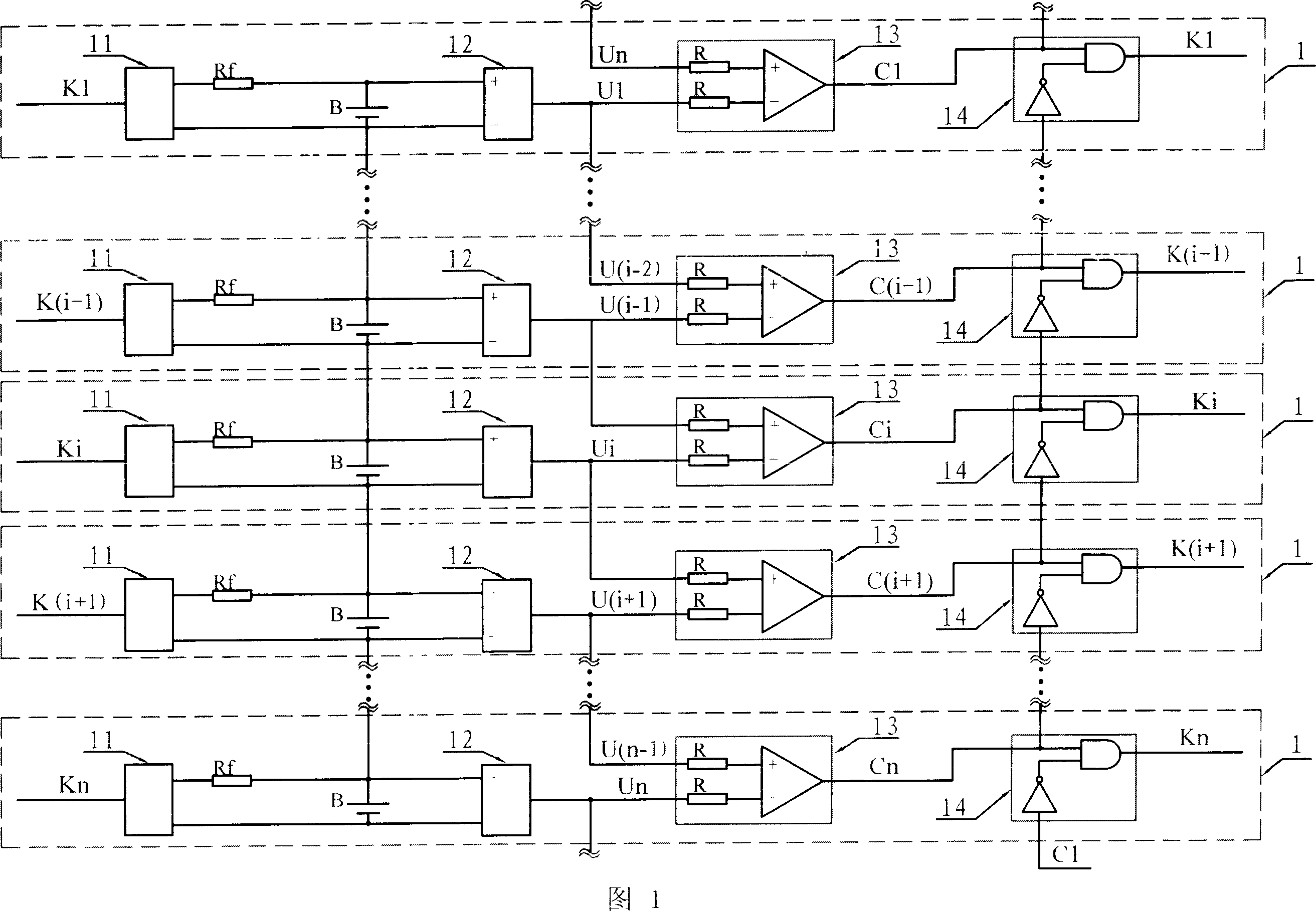
[0019] Specific embodiment 2: Refer to Fig. 1 to illustrate this embodiment, which is used to realize the single cell voltage equalization method in the power battery pack charging and discharging process described in the specific embodiment 1 during the charging and discharging process of the power battery pack The device is composed of n discharge and step-down control circuits 1, and the n discharge and step-down control circuits 1 are respectively corresponding to each single battery B in the power battery pack. The discharge step-down control circuit 1 is composed of a discharge relay 11, a discharge resistor Rf, a voltage measurement circuit 12, a voltage comparison circuit 13 and a control circuit 14; The positive and negative terminals of the voltage measurement circuit 12 are connected to the negative input of the voltage comparison circuit 13, the output of the voltage comparison circuit 13 is connected to an input terminal of the AND gate in the control circuit 14, a...

specific Embodiment approach 3

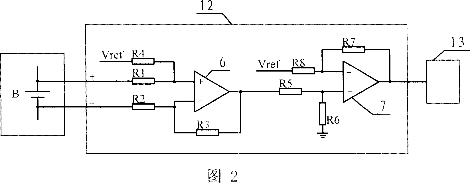
[0025] Specific embodiment three: refer to Fig. 2 to illustrate this embodiment, the voltage measuring circuit 12 described in the specific embodiment two, is made up of two-stage operational amplifier and eight resistances, the positive direction of one-stage operational amplifier 6, the negative direction input terminal The positive and negative terminals of the single battery B are respectively connected through the first resistor R1 and the second resistor R2, the positive input terminal of the first-stage operational amplifier 6 is connected with the reference voltage Vref through the fourth resistor R4, and the negative terminal of the first-stage operational amplifier 6 is connected with the reference voltage Vref through the fourth resistor R4. A primary feedback resistor R3 is connected between the input terminal and the output terminal, the output terminal of the primary operational amplifier 6 is connected to the positive input terminal of the secondary operational am...


PUM


Abstract

The voltage balancing method and device for every single cell of dynamic cell group during charging and discharging comprises: measuring (n) single cells in whole group with (n) voltage measuring circuits, comparing one single cell end voltage with its neighbor by a comparison circuit; if some single cell end voltage over its neighbor, outputting low-level signal from the comparison circuit to a control circuit; the latter operates the corresponding discharge relay to decrease this single cell voltage to keep consistency on end voltage of all single cells. This invention solves the problem that abnormal voltage of single cell affects whole cell group performance and life, and has wide application in cell testing system.

Description

technical field [0001] The invention relates to a single battery voltage equalization method and an equalizer in the charging and discharging process of a power battery pack. Background technique [0002] The power battery pack refers to a battery pack that can provide powerful power. It is suitable for hybrid vehicles, electric vehicles, portable radios, mobile data base stations, etc. The power battery pack is generally composed of multiple single cells connected in series. After multiple single cells are connected in series, due to the difference in the chemical properties of the single cells, there will often be unbalanced discharge of each single cell during use. The specific performance (1) When discharging, the energy of some single cells will be lower than that of other single cells, which means that its terminal voltage is lower than that of other single cells. When the voltage has not dropped to the protection voltage, the voltage of these single cells with low te...

Claims


Application Information

Patent Timeline
Patent Type & Authority Applications(China)
IPC IPC(8): H02J7/04
Inventor 崔刚杨孝宗刘宏伟左德承吴智博舒燕君董剑苗百利向琳张展罗丹彦王玲温东新阙子扬
Owner HARBIN INST OF TECH
Why Eureka
Try Eureka