Supercharge Your Innovation With Domain-Expert AI Agents!

Method, device and RF system for detecting the forward power

A forward power and power technology, applied in transmission control/equalization, communication between multiple stations, etc., can solve problems such as high cost, large size of radio frequency modules, and reduced power value accuracy of detection modules

Inactive Publication Date: 2007-08-15
HUAWEI TECH CO LTD
View PDF0 Cites 13 Cited by
  • Summary
  • Abstract
  • Description
  • Claims
  • Application Information

AI Technical Summary

Problems solved by technology

[0011] The defect of the existing technology is that the detection and calculation of the forward power requires a special detection module, which makes the radio frequency module bulky and high in cost; the sampling period of the A / D module is 100ms, which reduces the accuracy of the power value output by the detection module

Method used


Image

  • Method, device and RF system for detecting the forward power
  • Method, device and RF system for detecting the forward power
  • Method, device and RF system for detecting the forward power

Examples


Embodiment Construction

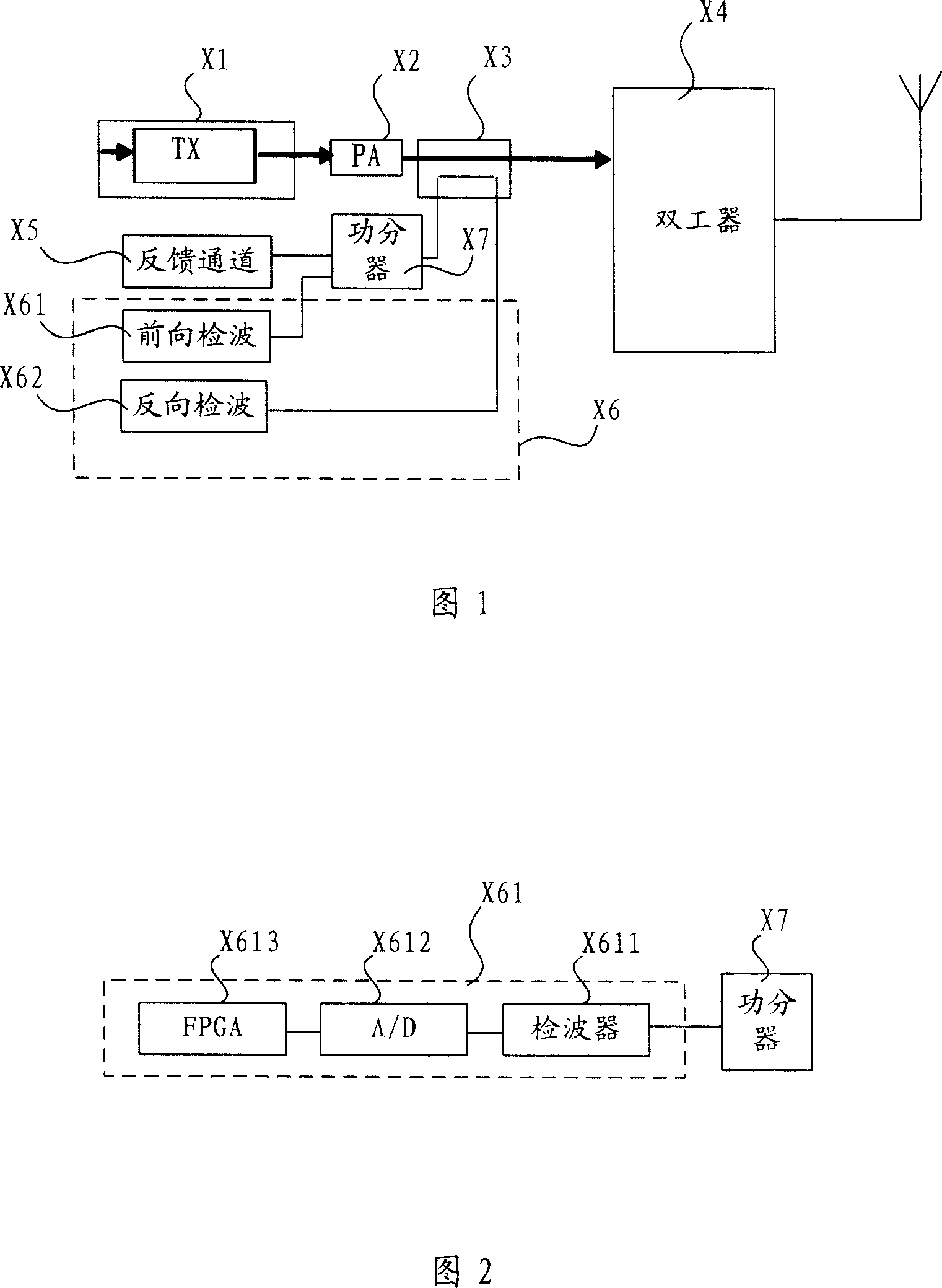
[0032] In the radio frequency module of the wireless base station, since the gain of the radio frequency channel will fluctuate with the change of the batch, temperature and frequency of the base station, through the downlink gain control function, the gain of the downlink channel, that is, the feedback channel, can be corrected to make the absolute value of the feedback channel of the radio frequency module The gain is relatively stable, which ensures that the feedback channel can generate stable output power for a fixed input power. In the embodiment of the present invention, the feedback channel is used for forward power detection.

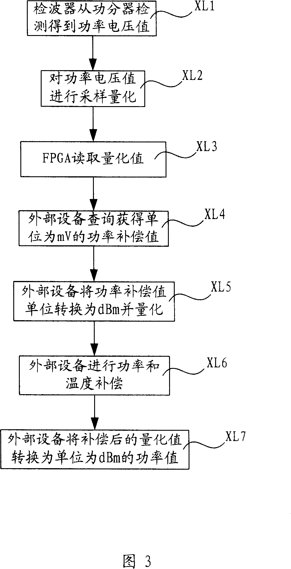
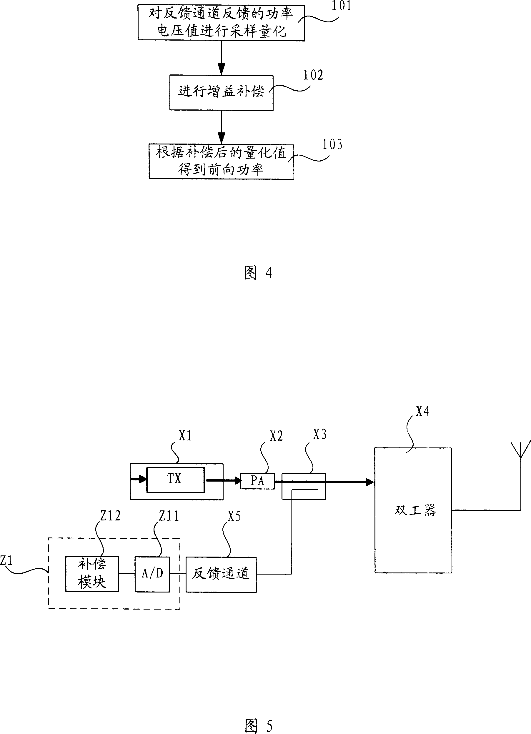
[0033] FIG. 4 is a flow chart of a preferred embodiment of the method for detecting forward power in the present invention. On the digital intermediate frequency of the feedback channel, the intermediate frequency power of the feedback signal can be counted first, and then the signal power of the antenna port can be calculated according to the g...


PUM


Abstract

The related method for detecting forward power comprises: using an A / D module to sample power voltage in feedback loop to obtain the quantized value; compensating gain with a compensation module, and obtaining the forward power. It also relates to a relative system. This invention can save a detection module and others to simplify structure and reduce cost, and then reduces cost on emitting RF signal.

Description

technical field [0001] The present invention relates to a method, device and radio frequency system for detecting forward power, in particular to a method for detecting forward power in a radio frequency module of a base station, a detection device and a radio frequency system based on the detection device. Background technique [0002] In the radio frequency module circuit of the existing wireless base station, to obtain the forward power, first a power quantization value is obtained through the detection circuit module, and then the power quantization value is compensated to obtain the forward power value. The forward power circuit system before detection and compensation is shown in Figure 1. The transmitting module (TX) X1 feeds the signal to the antenna through the power amplifier (PA) X2, coupler X3 and duplexer X4, and the power divider X7 divides The feedback power is distributed to the feedback channel X5 and the forward power detection circuit system X6. The feedba...

Claims


Application Information

Patent Timeline
IPC IPC(8): H04B7/005H04B7/26
Inventor 范钦槐
Owner HUAWEI TECH CO LTD
Features
  • R&D
  • Intellectual Property
  • Life Sciences
  • Materials
  • Tech Scout
  • Unparalleled Data Quality
  • Higher Quality Content
  • 60% Fewer Hallucinations
Learn More