Supercharge Your Innovation With Domain-Expert AI Agents!

Rotating machine

A technology of rotating electrical machines and rotors, applied in the field of reducing the induced voltage of rotating electrical machines, can solve the problems of large-scale rotating electrical machines, and achieve the effect of preventing large-scale

Active Publication Date: 2010-05-19
NISSAN MOTOR CO LTD
View PDF4 Cites 0 Cited by
  • Summary
  • Abstract
  • Description
  • Claims
  • Application Information

AI Technical Summary

Problems solved by technology

[0005] However, in the prior art described above, it is necessary to separately provide an actuator in order to switch between the short-circuit state and the normal state, which leads to a problem of increasing the size of the rotary electric machine.

Method used


Image

  • Rotating machine
  • Rotating machine
  • Rotating machine

Examples


Embodiment Construction

[0022] Hereinafter, embodiments of the present invention will be described in detail based on examples shown in the drawings.

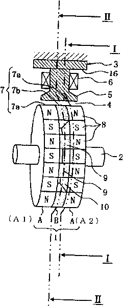
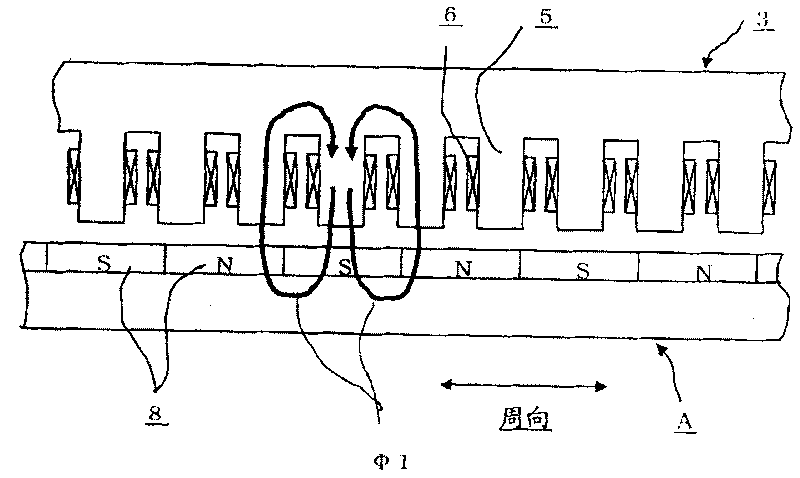
[0023] Figure 1A is a perspective view schematically showing the structure of a rotating electrical machine according to an embodiment of the present invention, Figure 1B yes Figure 1A The model diagram after the I-I section of ’s I-I section is expanded in the circumferential direction, Figure 1C yes Figure 1A The model diagram of the II-II section after it is expanded in the circumferential direction.

[0024] The rotating electric machine in this embodiment has a radial gap structure in which a stator 3 and a rotor 1 are arranged radially, and a radial gap (radial gap) 4 is provided between the stator 3 and the rotor 1 .

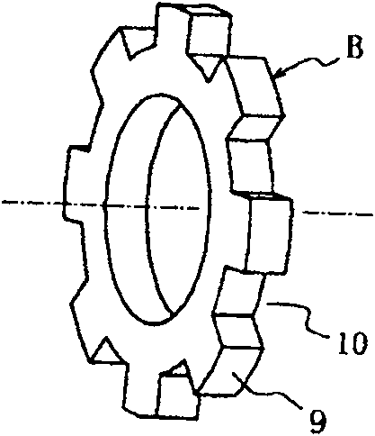
[0025] The rotor 1 of the rotating electrical machine is composed of a drive rotor A having a plurality of permanent magnets 8, 8... and a short-circuit rotor B for short-circuiting the permanent magnets 8, 8.... Here, the...


PUM


Abstract

The invention relates to a rotary electric motor, which can cause the magnetic flux of a permanent magnet (PM)short-circuit without needing an additional actuating mechanism such as an actuator and soon. The rotary electric motor comprises a drive rotor (A) provided with a plurality of permanent magnets; a short-circuit rotor (B) which can switch the magnetic flux of the permanent magnet betweenshort circuit condition and usual non-short circuit condition; a stator which faces to the drive rotor (A) and the short-circuit rotor (B) with a radial interval therebetween. The stator drives the drive rotor (A) through supplied recombination current, and also drives the short-circuit rotor (B) for switching between the short-circuit condition and the usual condition.

Description

technical field [0001] The present invention relates to a technique for reducing induced voltage of a rotating electric machine, particularly a technique for reducing magnetic flux flowing in a magnetic circuit formed between a rotor of a rotating electric machine and a stator of a rotating electric machine by short-circuiting the magnetic flux of a permanent magnet. technical background [0002] In a rotating electrical machine having permanent magnets, for example, Patent Document 1 describes a technique in which induced voltages increase when the rotor rotates at high speeds, and thus suppress the induced voltages by short-circuiting the magnetic fluxes of the permanent magnets when the rotors rotate at high speeds. [0003] The permanent magnet type rotating electrical machine described in Patent Document 1 includes: a rotor having a plurality of permanent magnets; a stator having a plurality of coils through which current is passed, and forming a magnetic circuit between...

Claims


Application Information

Patent Timeline
Patent Type & Authority Patents(China)
IPC IPC(8): H02K1/27H02K21/14
CPCH02K21/028H02K1/278H02K7/12H02K16/00H02K21/16
Inventor 涩川佑一
Owner NISSAN MOTOR CO LTD
Features
  • R&D
  • Intellectual Property
  • Life Sciences
  • Materials
  • Tech Scout
  • Unparalleled Data Quality
  • Higher Quality Content
  • 60% Fewer Hallucinations
Learn More