This helps you quickly interpret patents by identifying the three key elements:
Problems solved by technology
Method used
Benefits of technology
Problems solved by technology
[0018] Therefore, when the polarization direction of the input optical signal changes for some reason, the optical clock signal cannot be extracted stably.
Method used
Image
Click on the blue label to locate the original text in one second.
Reading with bidirectional positioning of images and text.
Examples
no. 1 approach
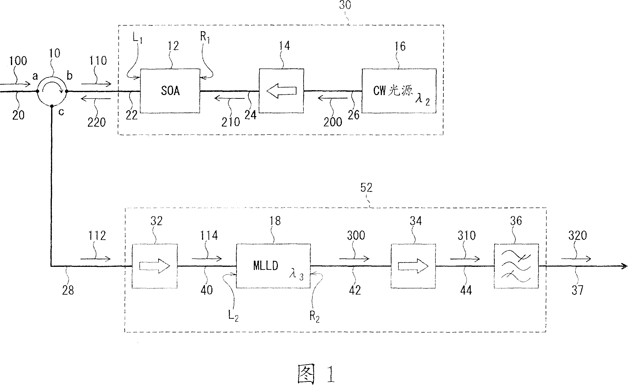
[0054] Referring to FIG. 1 , a first embodiment of an optical clock signal extracting device for realizing the first invention will be described. The optical clock signal extracting device of the first invention includes a first conversion unit 30 and a second conversion unit 52 . The first conversion unit 30 has a first optical converter 12 and a wavelength of λ 2The continuous wave light source 16 . To the first optical converter 12 input bit rate is f, wavelength is λ 1 The input optical signal 100, and the wavelength λ 2 of continuous wave light 200. In the first optical converter 12, using the input optical signal 100 and the wavelength λ 2 The cross-gain modulation effect exhibited by the continuous wave light 200 does not depend on the polarization direction of the input optical signal, generating a wavelength of λ 2 The optical signal 220 is generated in the middle of .
[0055] The second conversion unit 52 has a second light converter 18 . The intermediately g...
no. 2 approach
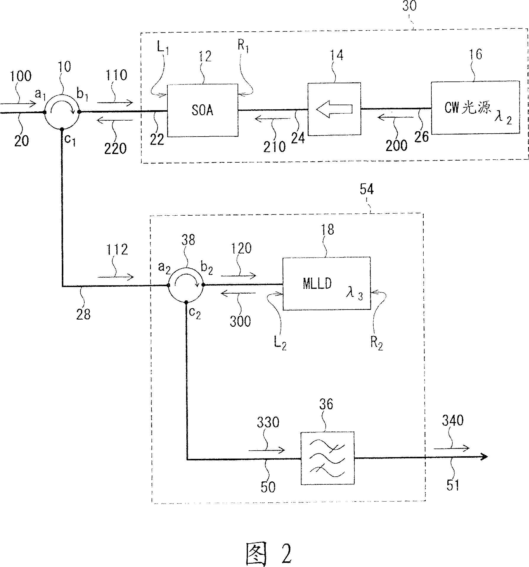
[0065] Referring to FIG. 2 , another mode different from the above-mentioned first embodiment for realizing the optical clock signal extraction device of the first invention will be described as a second embodiment. The difference between the second embodiment and the first embodiment lies in the structure of the second conversion unit. The structure of the first conversion unit is the same as that of the first embodiment, and therefore its description is omitted.
[0066] The second conversion unit 54 of the second embodiment has the optical circulator 38 , the second optical converter 18 and the optical bandpass filter 36 . The second optical converter 18 and the optical bandpass filter 36 can use the same devices as those in the first embodiment.
[0067] In Fig. 2, the optical circulator 10 utilizes the same optical circulator as the optical circulator utilized in the first embodiment, but here, in order to avoid confusion and for convenience, the three ports of the optic...
no. 3 approach
[0147] As a third embodiment, an optical clock signal extraction device and an optical clock signal extraction method according to the second invention will be described with reference to FIG. 10 . Fig. 10 is a schematic structural block diagram of the optical clock signal extraction device.
[0148] The optical clock signal extraction device of the second invention is different from the optical clock signal extraction device and the first converting unit of the first invention described above. As the first optical converter included in the first conversion unit, an SOA can be used, but unlike the optical clock signal extraction device of the first invention, a saturable absorber or an EAM cannot be used. That is, in the optical clock signal extraction method of the second invention, the first conversion step is realized by using XGM instead of XAM.
[0149] If the first conversion step is realized by using XGM, the speed becomes slower than when it is realized by using XAM a...
PUM
Abstract
The present invention is an optical clock signal extraction device and method which extracts optical clock signal independent of the polarized light direction of the input light signal. The apparatus comprises first conversion means and second conversion means for enabling to extract an optical clock signal without depending on the polarization direction of an input optical signal. The first conversion means comprises a first optical converter and a continuous wave light source of which wavelength is lambda2, where an input optical signal of which wavelength is lambda1 and continuous wave light of which wavelength is lambda2 are input to the first optical converter, and an intermediate optical signal of which wavelength is lambda2 is generated and output without depending on the polarization direction of the input optical signal. The second conversion means has a second optical converter, where the intermediate optical signal is input to the second optical converter, and an optical clock signal of which wavelength is lambda3 is generated and output by the passive mode locking operation of the second optical converter. The input optical signal is input from the end face L 1 of the first optical converter, and the continuous wave light of which wavelength is lambda2 is input to the first optical converter from the other end face of the first optical converter. The intermediate optical signal is output from the end face of the first optical converter and input to the end face of the second optical converter. The optical clock signal is output from the other end face of the second optical converter.
Description
technical field [0001] The present invention relates to an optical clock signal extraction device for optical repeaters and the like used in long-distance and large-capacity optical fiber communication systems, in particular to a device for extracting fast optical clock signals exceeding the upper limit operating speed of electronic equipment. Background technique [0002] Long-distance and large-capacity transmission of optical communication networks have been developed. As the transmission distance increases, optical loss in the optical transmission path, a decrease in the S / N ratio due to the use of multiple stages of optical amplifiers, and the dispersion of the group velocity of the optical fiber or nonlinear optical effects in the optical fiber occur. Waveform distortion causes a problem of deterioration in the quality of an optical signal due to the above-mentioned circumstances. The occurrence of frequency waveform distortion and time waveform distortion becomes a m...
Claims
Application Information
Patent Timeline
Application Date:The date an application was filed.
Publication Date:The date a patent or application was officially published.
First Publication Date:The earliest publication date of a patent with the same application number.
Issue Date:Publication date of the patent grant document.
PCT Entry Date:The Entry date of PCT National Phase.
Estimated Expiry Date:The statutory expiry date of a patent right according to the Patent Law, and it is the longest term of protection that the patent right can achieve without the termination of the patent right due to other reasons(Term extension factor has been taken into account ).
Invalid Date:Actual expiry date is based on effective date or publication date of legal transaction data of invalid patent.

