Crosscutting tool for high-speed crosscutting

A cross-cutting and tooling technology, applied in the direction of knives, manufacturing tools, shearing devices, etc. used in shearing machines, can solve the problems of reduced operation efficiency, large energy consumption, noise level and total strain, etc., to achieve excellent contact Effect

Inactive Publication Date: 2007-08-29
MORPHIC TECH
View PDF2 Cites 3 Cited by
  • Summary
  • Abstract
  • Description
  • Claims
  • Application Information

AI Technical Summary

Problems solved by technology

Consequently, large dimensional deviations frequently occur with large diameter raw materials (>12 mm), which are produced by rolling (oppositely drawn and surface ground rods and wires, the rods and wire material embodies better dimensional accuracy), the above-mentioned large dimensional deviations have been proved to reduce the efficiency of the operation, resulting in greater energy consumption, noise due to the use of greater force and impact when using extra-large machinery level and total strain

Method used


Image

  • Crosscutting tool for high-speed crosscutting
  • Crosscutting tool for high-speed crosscutting
  • Crosscutting tool for high-speed crosscutting

Examples


Embodiment Construction

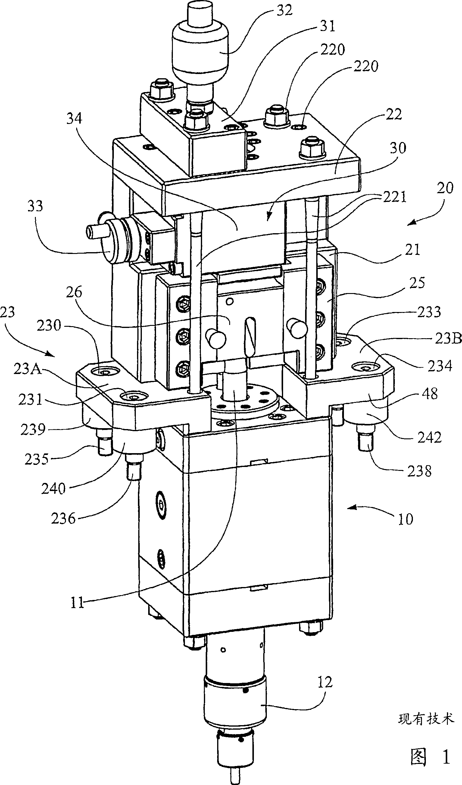
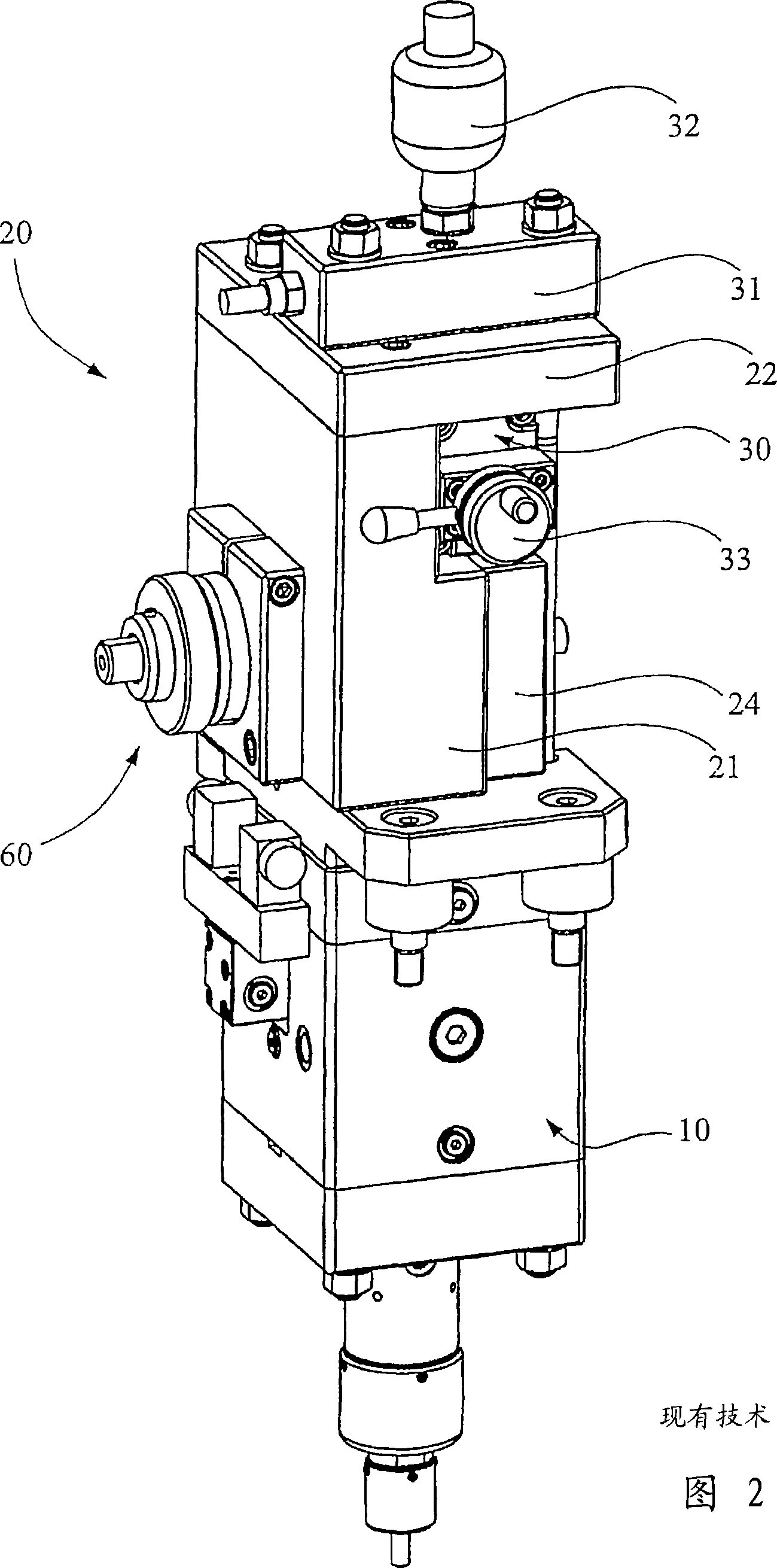
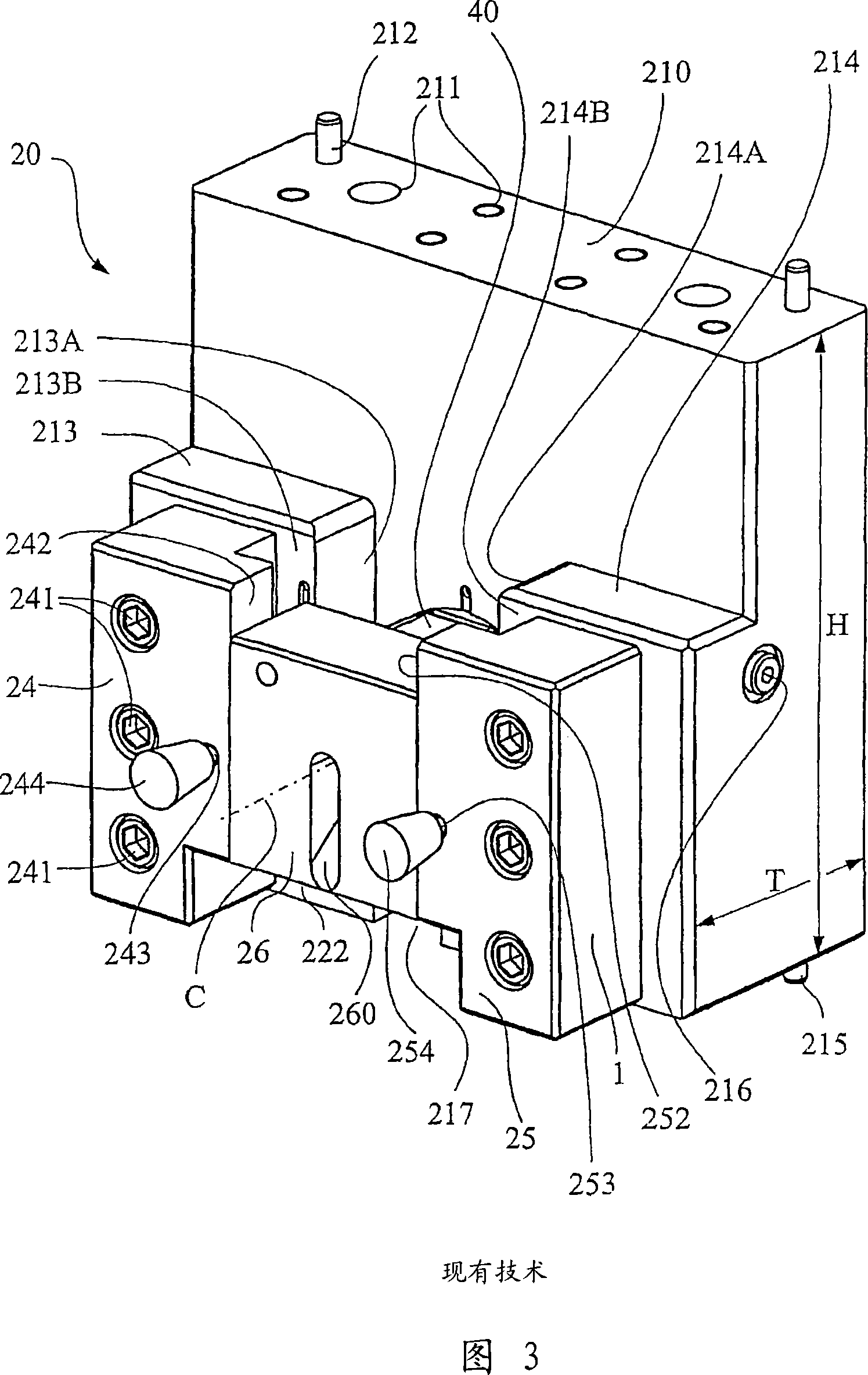
[0037] Fig. 1 illustrates a perspective view from an obliquely upward direction of a modular unit in the prior art. The tool device comprises a percussion unit 10 , a tool housing 20 and a damper 30 . A movable cross-cutting tool 40 and a fixed cross-cutting tool 50 are provided within the tool housing 20 . The impact piston 11, driven by the impact unit 10, is capable of giving a high-kinetic blow from the bottom up to the movable cross-cutting tool 40 in a known manner, the fixed cross-cutting tool 50 resting on the workpiece (not shown) to be cut. Apply a resistance to it. The damper 30 is arranged to resist the impact action of the movable cross-cutting tool 40 after the cut has been completed. The percussion unit 10 and damper 30, associated damper housing 34, hydraulic block 31 and pressure accumulator 32 will not be described in detail here as they are not relevant to the invention. However, it should be mentioned that the protruding wheel 33 on the damper 30 constit...


PUM


Abstract

The present invention relates to a Crosscutting tool for high-speed crosscutting, which crosscutting tool (40; 50) comprises a body (43,420; 52, 520) having a through-hole (41, 51), for a rod (W) to be cut, and a cutting edge (46) delimiting at least a portion of said through-hole (41, 51), wherein said cutting edge (46) is formed by at least two cutting jaws (401, 402; 403, 404) positioned within and supported by said body (43, 420; 52, 520).

Description

technical field [0001] The invention relates to a cross-cutting tool for high-speed cross-cutting (cross-cutting), said cross-cutting tool comprising a body with a through hole for the bar to be cut, and a cutting edge limiting at least a portion of the through hole. Background technique [0002] For example, according to US Pat. No. 3,735,656, a tool arrangement for high-speed cross-cutting is known. Therefore, it is also known to use the aforementioned tool devices for cutting rod-shaped materials by means of a high energy supply rate. Despite the many potential advantages of using this method, it is not commonly used and established in the manufacturing industry. The reason why this technique could not be established on a larger scale is due to the lack of structure of the tool and the resulting undesired interruption of production. This deficiency is manifested in the fact that it is often not possible to achieve a sufficiently high degree of accuracy in aligning the ...

Claims


Application Information

Patent Timeline
Patent Type & Authority Applications(China)
IPC IPC(8): B21F11/00B23D15/04B23DB23D15/12B23D35/00
CPCY10T83/483B23D15/12B21F11/00B23D35/001B23D15/04
Inventor 哈肯·奥尔森安德斯·达尔伯格
Owner MORPHIC TECH
Why Eureka
Try Eureka