
Comprehensive pneumatic measuring device for link rod

A pneumatic measurement and connecting rod technology, applied in the direction of measuring devices, fluid devices, instruments, etc., can solve the problems of low measurement efficiency, high labor intensity, large measurement error, etc., achieve high measurement efficiency, high measurement accuracy, and reduce detection cost effect

Inactive Publication Date: 2007-09-05
SHENGRUI TRANSMISSION
View PDF0 Cites 16 Cited by
  • Summary
  • Abstract
  • Description
  • Claims
  • Application Information

AI Technical Summary

Problems solved by technology

[0003] For the internal combustion engine connecting rod, since it has two holes, there are many dimensional and shape tolerances to be tested, such as the parallelism of the two holes, the center distance, and the cylindricity and size of each hole, etc. Usually, multiple sets are required The inspection tool is completed by many people, the measurement error is large, the measurement efficiency is low, it takes up a lot of manpower, and the labor intensity is high, which can no longer meet the requirements of the main engine factory.
There is no record in the known technology of a pneumatic measuring device specially used for measuring the shape and position tolerances of connecting rods, especially a pneumatic measuring device suitable for measuring the parallelism of two holes

Method used


Image

  • Comprehensive pneumatic measuring device for link rod
  • Comprehensive pneumatic measuring device for link rod
  • Comprehensive pneumatic measuring device for link rod

Examples


Embodiment Construction

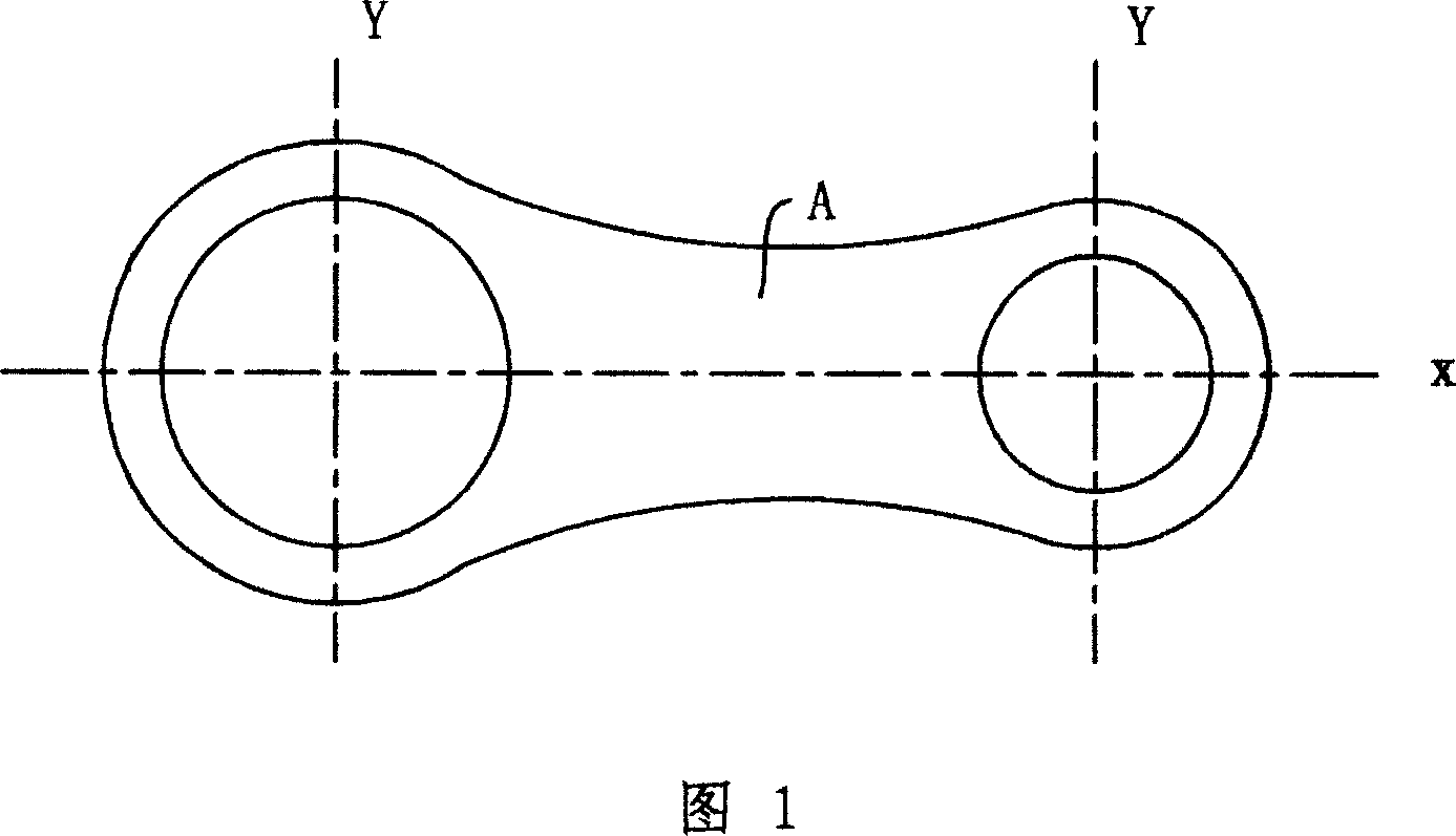
[0020] Fig. 1 is a top view of a connecting rod A of an internal combustion engine. For the convenience of description, the direction passing through the centerlines of the two holes is defined as the X direction, and the direction perpendicular to the centerlines of the two holes is defined as the Y direction.

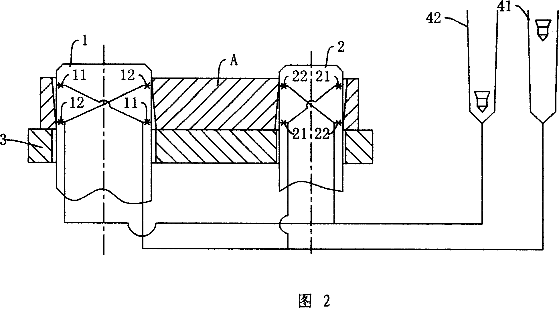
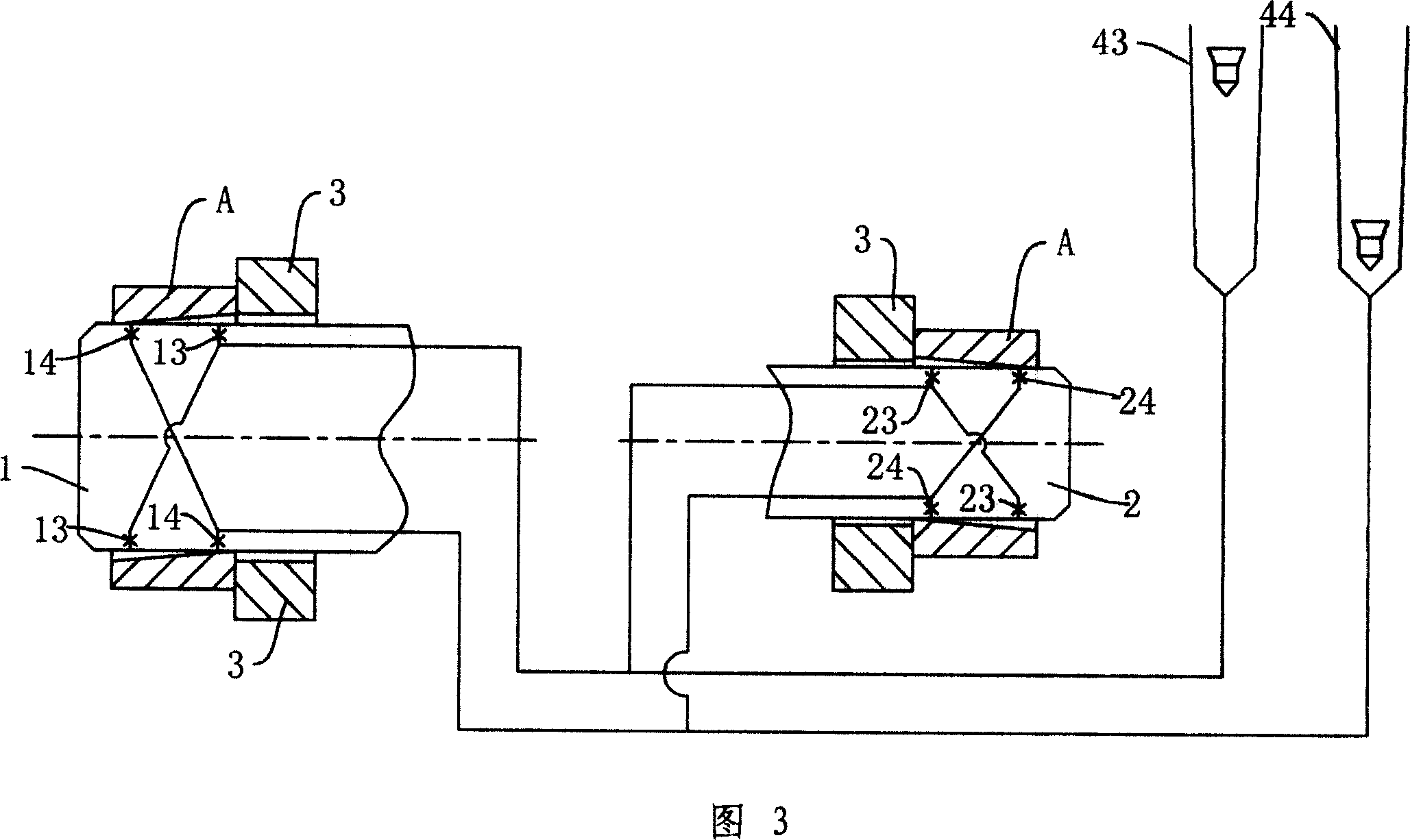
[0021] The present invention mainly includes two measuring heads, which are respectively provided with several measuring branches that can be connected with corresponding data indicating units of the pneumatic measuring instrument, and these data indicating units can intuitively measure the two measuring heads. data is displayed. The pneumatic measuring instrument adopts a buoy-type pneumatic measuring instrument, and of course a digital pneumatic measuring instrument can also be used. The data indication unit of the buoy-type pneumatic measuring instrument usually adopts such a structure, and a buoy is set in a glass tube with a scale. One end of the glass tube is co...


PUM


Abstract

An integrated pneumatic measurement device used on link is prepared as setting the first measurement branch for measuring x directional parallelism of link two holes axle, the second measurement branch for measuring Y directional parallelism of link two hole axle, the third measurement branch for measuring center distance of link two holes, the fourth measurement branch for measuring the first hole cylindricity of link and the fifth measurement branch for measuring the second hole cylindricity of link separately on the first and the second measurement heads.

Description

technical field [0001] The invention relates to the technical field of pneumatic measuring devices, in particular to a pneumatic measuring device for comprehensive measurement of connecting rods. Background technique [0002] The pneumatic measurement method uses compressed air as the medium, and uses the characteristics of the flow and pressure of the air in the pipeline to change with the geometric size or shape of the pipeline to convert the change in size or displacement into flow or pressure change, so as to achieve high precision. Measurement, the tool used in the pneumatic measurement method is a pneumatic measuring instrument, which is used in conjunction with a pneumatic measuring device. Because it can perform non-contact measurement, high-pressure airflow is sprayed on the surface of the workpiece and has self-cleaning effect, low environmental requirements, simple structure, convenient operation and maintenance, and low cost, it is widely used in machinery indust...

Claims


Application Information

Patent Timeline
IPC IPC(8): G01B13/00G01B13/12G01B13/18
Inventor 高俊平叶培新
Owner SHENGRUI TRANSMISSION
Learn More