Ultrasonic positioner and its positioning method
A positioning device, ultrasonic technology, applied in the direction of measurement device, sound wave re-radiation, radio wave measurement system, etc., can solve problems such as increasing production cost, difficulty in installation and debugging, reducing battery life, increasing the volume of signal pen, etc., to avoid The effect of external light interference, reducing battery power consumption, and improving anti-interference
- Summary
- Abstract
- Description
- Claims
- Application Information
AI Technical Summary
Problems solved by technology
Method used
Image

Examples
Embodiment 1
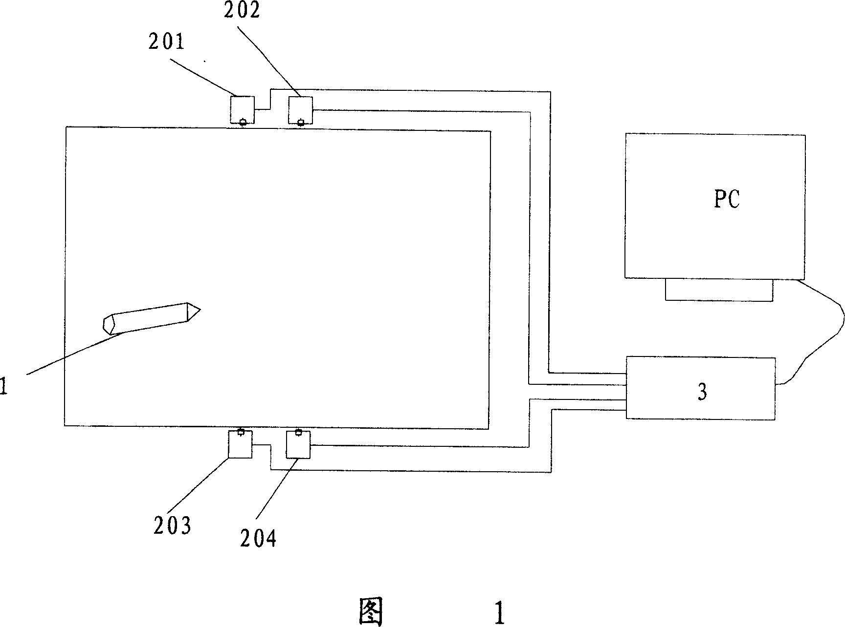
[0031] The structure diagram of the ultrasonic positioning device of the present invention is shown in FIG. 1 , which includes an ultrasonic signal pen 1 , ultrasonic receiving modules 201 , 202 , 203 , and 204 located on two opposite edges of the writing plane, and a main processing module 3 . The ultrasonic receiving modules 201 , 202 , 203 , 204 are connected to the main processing module 3 by power lines, ground lines, and ultrasonic signal lines, respectively.
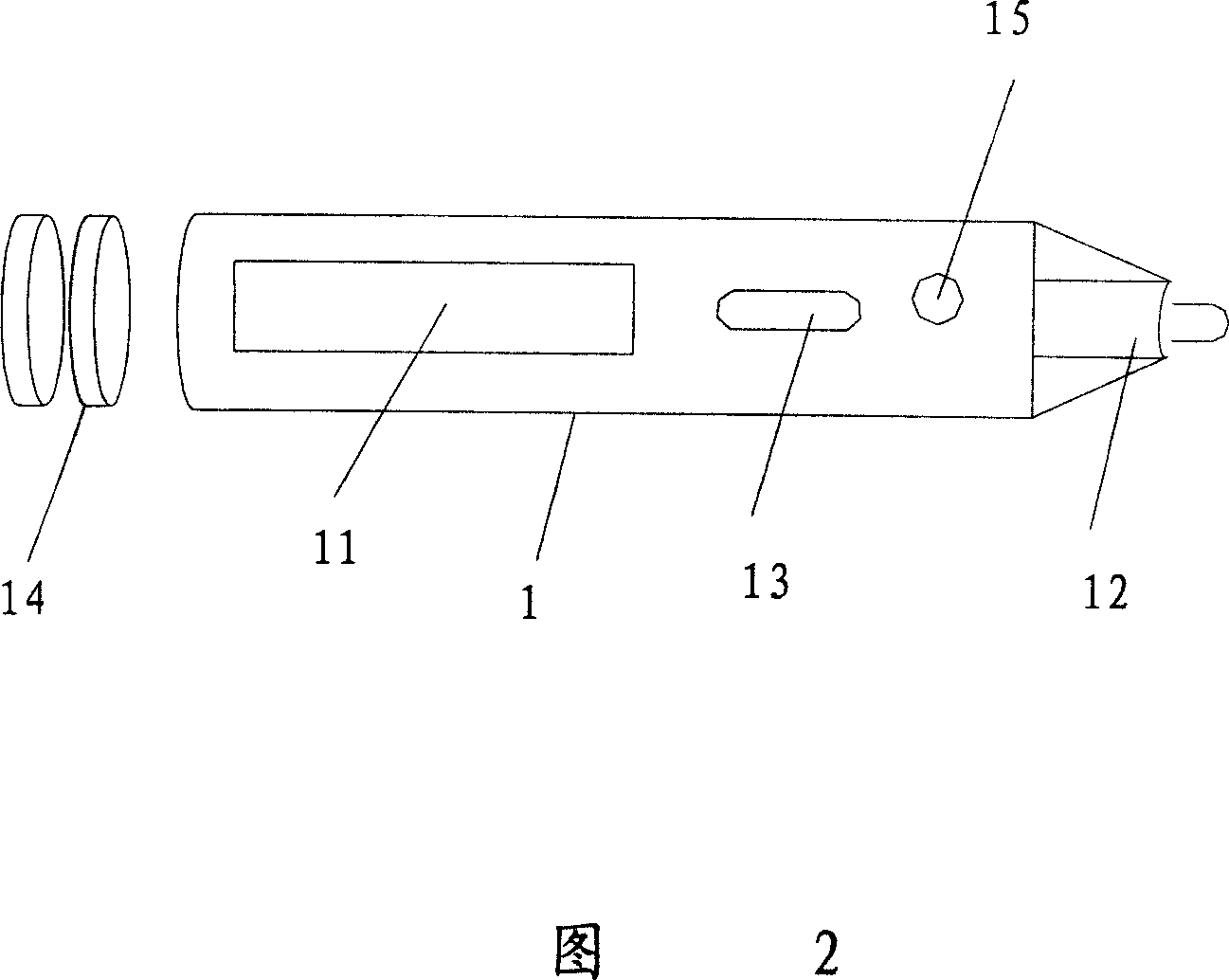
[0032] The schematic diagram of the structure of the ultrasonic signal pen 1 is shown in Figure 2: it includes a battery 14, an ultrasonic transmitting circuit 11, a light touch switch 13 and a force sensor 15 for controlling the emission of ultrasonic waves, and the end near the tip of the pen is provided with an ultrasonic transmitting circuit. The module 11 is connected with an ultrasonic emitting element 12 .
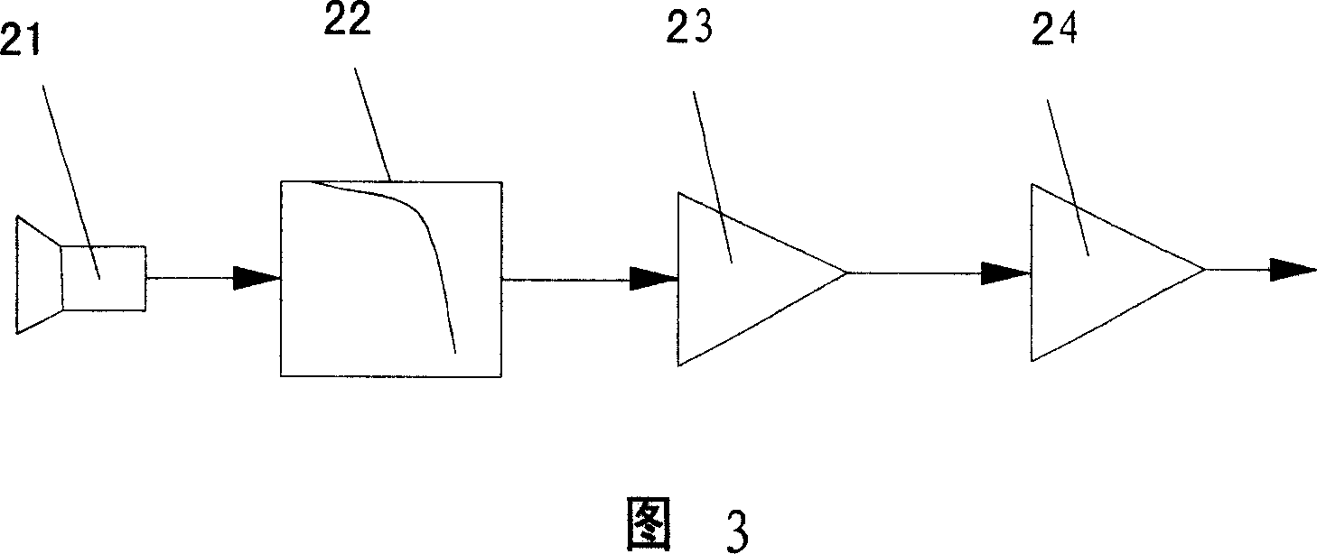
[0033] The principle schematic diagram of the ultrasonic receiving module is shown in FIG. 3 : it in...
Embodiment 2
[0049] The ultrasonic positioning device and positioning method of the present invention can also be applied to an m*N large-screen splicing wall, such as the m*N large-screen splicing wall shown in Figure 8, wherein m and N represent the number of columns and rows of the splicing wall respectively Number, where N can be one or more rows within the maximum range that the ultrasonic transducer can detect. Multiple receiving modules are placed on the screen splicing wall. Every two adjacent splicing walls can be defined in a positioning area, that is, four ultrasonic receiving modules sharing a single detection area. Every four ultrasonic receiving modules can detect ultrasonic waves within a certain range. The signals are then sent to the main processing modules in their respective detection areas. Firstly, the position coordinates of their respective detection areas are determined, and then a main control board coordinates the synchronous work of the main processing modules in ...
Embodiment 3
[0051] Referring to Fig. 9, the positioning algorithm principle of the ultrasonic positioning device according to Embodiment 3 of the present invention is as follows: the ultrasonic receiving modules 201, 202, 203, and 204 are respectively located on the same straight line that is not parallel to the writing plane, and the straight line can be perpendicular to the writing plane of the positioning range. It can also be as shown in the figure, the distances from the ultrasonic transducers 211, 212, 213, 214 of the receiving modules 201, 202, 203, 204 to the writing plane are H1, H2, H3, H4 respectively, and P represents the plane The coordinates of each receiving module are divided into (p1x, p1y, H1), (p2x, p2y, H2), (p3x, p3y, H3), (p4x, p4y, H4) for any point to be positioned within The arrival times of the ultrasonic waves are t1, t2, t3, t4 respectively, and the deviation from the transmission time of the actual ultrasonic waves is Δt; the ultrasonic emission film 12 on the ...
PUM
 Abstract
Description
Claims
Application Information
 - Generate Ideas
- Intellectual Property
- Life Sciences
- Materials
- Tech Scout
- Unparalleled Data Quality
- Higher Quality Content
- 60% Fewer Hallucinations
Browse by: Latest US Patents, China's latest patents, Technical Efficacy Thesaurus, Application Domain, Technology Topic, Popular Technical Reports.
© 2025 PatSnap. All rights reserved.Legal|Privacy policy|Modern Slavery Act Transparency Statement|Sitemap|About US| Contact US: help@patsnap.com