Supercharge Your Innovation With Domain-Expert AI Agents!

Ultrathin wall rolling bearing

A rolling bearing, ultra-thin-wall technology, applied in rolling contact bearings, bearings, bearings in rotating motion, etc., can solve problems such as short life and achieve the effect of preventing abrasion

Inactive Publication Date: 2007-09-12
NTN CORP
View PDF3 Cites 1 Cited by
  • Summary
  • Abstract
  • Description
  • Claims
  • Application Information

AI Technical Summary

Problems solved by technology

[0009] In addition, when the bearing is transported, especially when it is exported to overseas, abrasion may occur, and the peeling that occurs starting from this abrasion will become the cause of short life.

Method used


Image

  • Ultrathin wall rolling bearing
  • Ultrathin wall rolling bearing
  • Ultrathin wall rolling bearing

Examples


Embodiment Construction

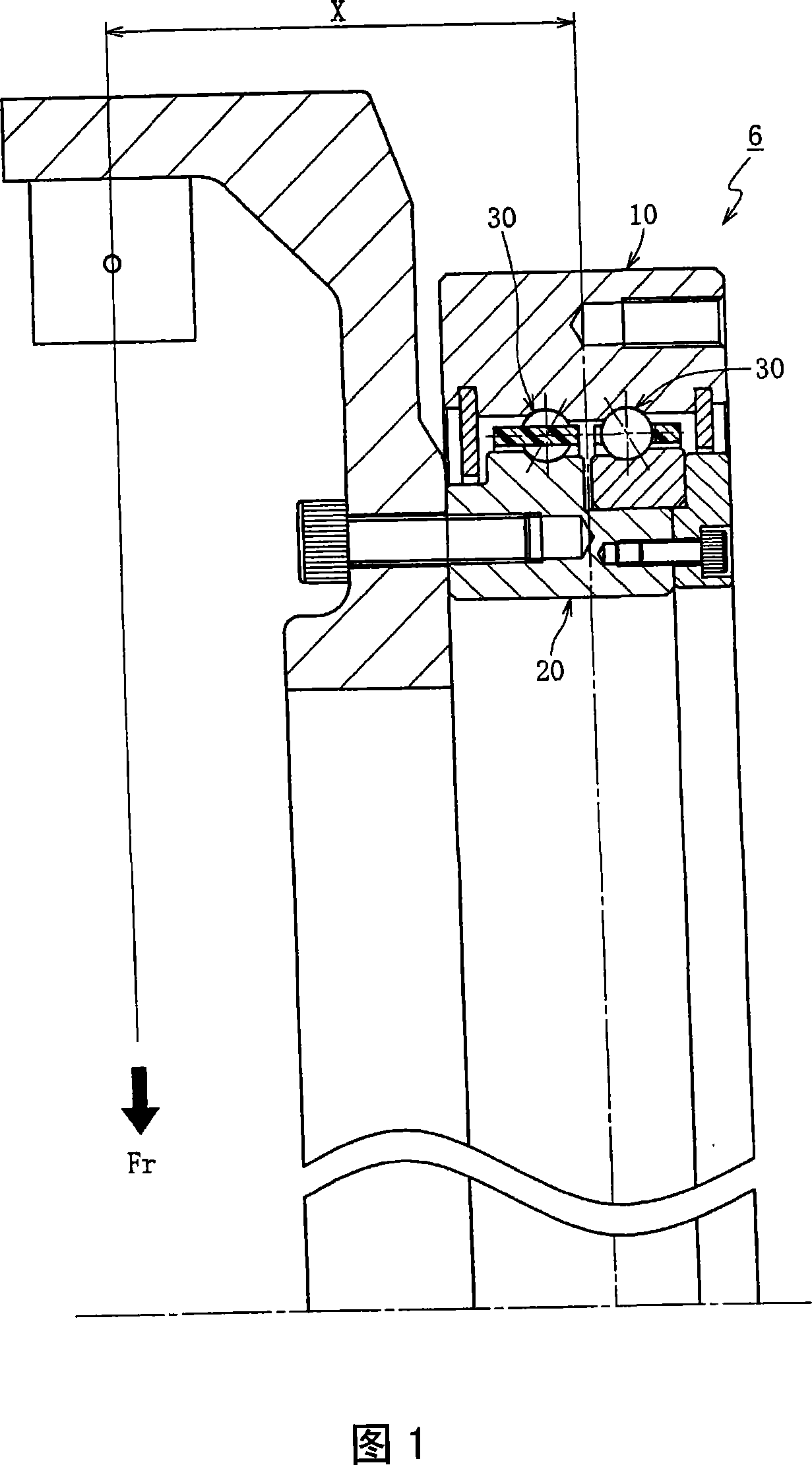
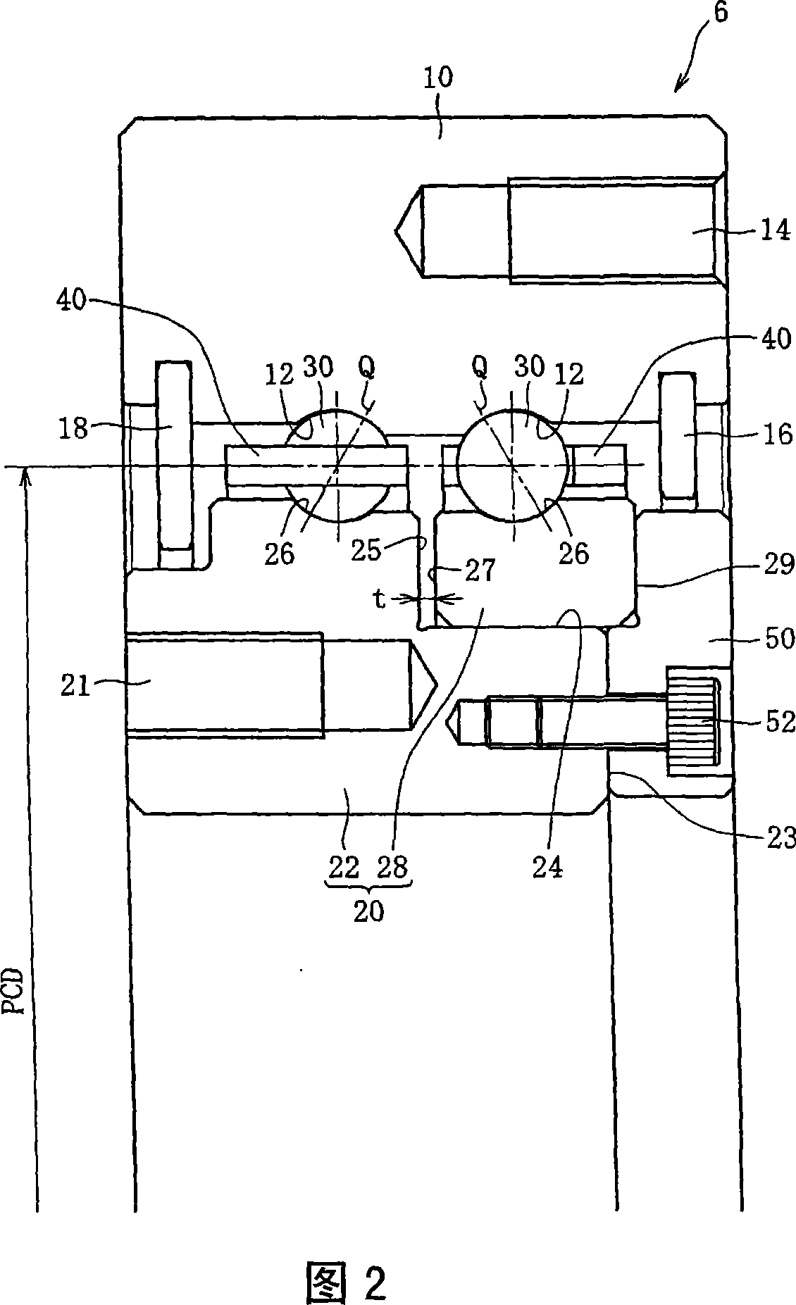
[0024] Hereinafter, embodiments of the present invention will be described with reference to the drawings. Here, FIG. 1 shows the structure of the bearing 6 of the CT scanner shown in FIG. 4 , and FIG. 2 is an enlarged view of main parts in FIG. 1 .

[0025] As shown in FIG. 2, the main components of the bearing 6 include an annular outer member 10, an annular inner member 20 concentrically disposed on the inner peripheral side of the outer member 10, and a ring-shaped inner member 20 sandwiched between the outer members. Multiple rows of rolling elements 30 between 10 and the inner member 20, cages 40 that hold the rolling elements 30 of each row at predetermined intervals in the circumferential direction, and seal rings 16 that seal the openings at both ends of the bearing, 18. And a preload imparting member S for imparting preload to the bearing.

[0026] This bearing 6 is a multi-row bearing in which the number of rows of rolling elements 30 is two. Among them, balls 30 ...


PUM


Abstract

An ultrathin-walled rolling bearing enabling prevention of fretting during transportation, an increase in moment rigidity of the bearing, and suppression of an effect of a centrifugal force generated in high-speed rotation. A material of the races (an outer member (10) and an inner member (20)) of the ultrathin-walled rolling bearing is allowed to be different from a material of rolling elements (balls (30) ) . For example, the races (10, 20) are formed of steel, and the rolling elements (30) are formed of a material having a modulus of direct elasticity of 1. 5 times that of the steel or higher. Alternatively, the races (10, 20) are formed of steel, and the rolling elements (30) are formed of a material having a density of 1 / 2 or less of that of the steel.

Description

technical field [0001] The present invention relates to an ultra-thin rolling bearing used in industrial robots, machine tools, medical equipment and the like. Background technique [0002] FIG. 4 shows an example of a CT scanner as a medical device. In the CT scanning device, the X-rays generated by the X-ray device 1 are irradiated to the subject 4 through the wedge-shaped filter 2 and the slit 3, wherein the wedge-shaped filter 2 makes the intensity distribution of the X-ray uniform, and the slit 3 limits the intensity distribution . The X-rays passing through the subject 4 are received by the detector 5, converted into electrical signals, and sent to a computer not shown. X-ray tube device 1, wedge-shaped filter 2, slit 3, detector 5 and other components are installed on the approximately cylindrical rotating stand 8 through the bearing 6, and the rotating stand 8 can be freely rotatably supported on the fixed stand 7 , rotates around the object 4 as the rotating gant...

Claims


Application Information

Patent Timeline
Patent Type & Authority Applications(China)
IPC IPC(8): F16C19/18F16C33/62F16C33/32
CPCF16C2300/14A61B6/035F16C33/60F16C33/303F16C33/3812F16C33/32F16C19/184F16C33/416F16C2208/72F16C2240/70F16C2240/80F16C2316/10
Inventor 平松研吾大矢洋右
Owner NTN CORP
Features
  • R&D
  • Intellectual Property
  • Life Sciences
  • Materials
  • Tech Scout
  • Unparalleled Data Quality
  • Higher Quality Content
  • 60% Fewer Hallucinations
Learn More