Supercharge Your Innovation With Domain-Expert AI Agents!

Image encoding apparatus, image decoding apparatus and control method therefor

An image encoding and encoding technology, which is applied in image encoding, image communication, image data processing, etc., can solve the problem of K parameter becoming larger and achieve good compression performance

Active Publication Date: 2010-05-26
CANON KK
View PDF3 Cites 0 Cited by
  • Summary
  • Abstract
  • Description
  • Claims
  • Application Information

AI Technical Summary

Problems solved by technology

Therefore, there will still be such a problem: for example, in the case of encoding information sources whose statistical properties are greatly changed due to insufficient state separation, when a large prediction error occurs, multiple The prediction error brings the influence of the k parameter becoming larger

Method used


Image

  • Image encoding apparatus, image decoding apparatus and control method therefor
  • Image encoding apparatus, image decoding apparatus and control method therefor
  • Image encoding apparatus, image decoding apparatus and control method therefor

Examples


no. 1 Embodiment approach

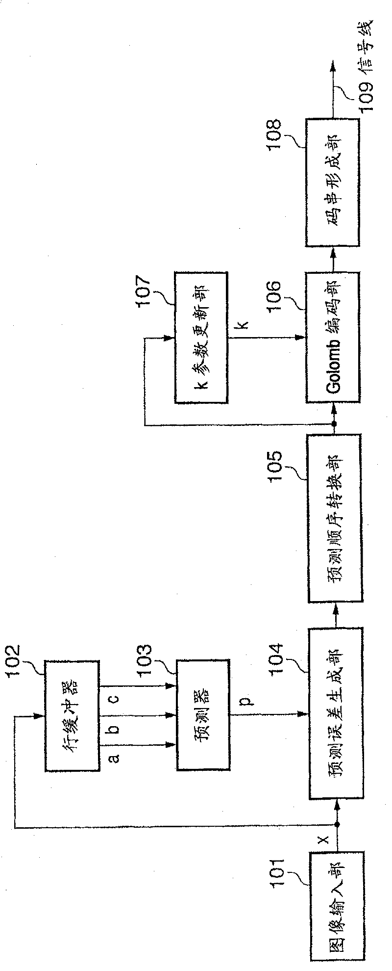
[0060] figure 1 is a block configuration diagram showing the functional configuration of the image processing device according to the present embodiment.

[0061] Such as figure 1 As shown, the image processing device for image coding according to this embodiment includes: an image input unit 101, a line buffer (line buffer) 102, a predictor 103, a prediction error generation unit 104, a prediction order conversion unit 105, a Golomb encoding part 106, k parameter update part 107 and code string forming part 108. exist figure 1 109 represents a signal line.

[0062] Below, refer to figure 1 Image coding processing performed by the image processing device according to this embodiment will be described. Here, the encoding target image is taken as monochrome image data in which each pixel is composed of 8-bit (range of 0 to 255) pixel data representing a luminance value or a density value. However, this method can be similarly applied to color images represented by mult...

no. 2 Embodiment approach

[0132] Next, a second embodiment will be described. In the image processing device according to the first embodiment, correction is performed by increasing or decreasing the coding parameter k every time the code to be coded is outside the optimum code range. In such a case, there is an advantage of being able to respond quickly to changes in the statistical properties of the information source, but stability will be a problem in information sources whose properties change little.

[0133] For example, consider the probability distribution f(n, k)=(1 / 2)^L(n, k) with the maximum coding efficiency among the respective k parameters. L(n, k) is the code length when Golomb encoding is performed on the coding object symbol n with the coding parameter k, and is given by L(n, k)=k+1+floor(n / (2^k)). x^y means x raised to the power of y, and floor(x) means a function that returns the largest integer not exceeding x.

[0134] Figure 7 Indicates the probability distribution f(n, 1) wh...

no. 3 Embodiment approach

[0170] In the above-mentioned second embodiment, the method of reducing the k parameter when the symbol of the region 51 is generated twice is shown, but the number of occurrences to be updated may be changed according to the k parameter. An example of this will be described as a third embodiment.

[0171] The block diagram of the image processing device according to the third embodiment is different from that described in the second embodiment. Figure 10 The same, only the processing of the k parameter update unit 1002 is different. Hereinafter, the processing of the k-parameter update unit 1002 in the third embodiment will be described.

[0172] The k parameter update unit 1002 of the third embodiment holds Figure 12 The shown correspondence table of index value i and parameter k, and array I[S] storing index value i for 365 state numbers S classified by the context generation unit 1001 . All elements of the array I[S] are set to an initial value (here, 4) at the time o...


PUM


Abstract

The present invention is able to determine an encoding parameter using a simple method with little processing load or memory cost, and enables encoding of image data with excellent compression performance. To this end, a prediction error generating unit of an encoding apparatus according to the present invention calculates the difference (prediction error) between a pixel of interest and a predicted value. A prediction order conversion unit converts the prediction error to a non-negative integer, and outputs the non-negative integer as a prediction order M(e). A Golomb encoding unit performs encoding in accordance with a k parameter supplied from a k parameter updating unit. The k parameter updating unit updates the k parameter for use in the next updating based on the prediction order M(e) of the pixel of interest and the k parameter supplied to the Golomb encoding unit.

Description

technical field [0001] The present invention relates to an image encoding device, an image decoding device, and their control methods. Background technique [0002] As a form of entropy coding used for image coding, there are a form using a static probability distribution model and a form based on a dynamic model. The method using a static probability distribution model is a method of investigating or assuming the properties of an information source, preparing a probability distribution model in advance, and performing coding suitable for the model. In addition, the format using the dynamic probability distribution model is a format in which the properties of the information source are learned during the encoding process, and the encoding is performed while dynamically changing the probability distribution model. [0003] Here, two examples of lossless coding of multivalued images are given. [0004] In the lossless compression coding method specified by JPEG recommended b...

Claims


Application Information

Patent Timeline
Patent Type & Authority Patents(China)
IPC IPC(8): H04N7/26H04N7/32H04N1/41G06T9/00H03M7/40H04N1/417
CPCH04N7/26106H04N19/00569H04N19/50H04N19/91H03M7/40H04N1/417H04N19/42
Inventor 梶原浩
Owner CANON KK
Features
  • R&D
  • Intellectual Property
  • Life Sciences
  • Materials
  • Tech Scout
  • Unparalleled Data Quality
  • Higher Quality Content
  • 60% Fewer Hallucinations
Learn More