Air foil bearing having a porous foil

A foil bearing and foil technology, which is applied in the field of air foil bearings, can solve the problems of difficult performance, insufficient vibration damping capacity of air foil bearings, and the reduction of the maximum rotational speed of rotating bodies, etc.

Inactive Publication Date: 2007-09-26
KOREA INST OF SCI & TECH
View PDF0 Cites 22 Cited by
  • Summary
  • Abstract
  • Description
  • Claims
  • Application Information

AI Technical Summary

Problems solved by technology

[0010] Moreover, if the damping capacity of the air foil bearing is insufficient, the maximum rotational speed of the rotating body that the bearing can withstand will be reduced
Therefore, it is difficult for the air foil bearings of the prior art as described above to exhibit their full performance in a turbine system requiring high rotational speeds

Method used


Image

  • Air foil bearing having a porous foil
  • Air foil bearing having a porous foil
  • Air foil bearing having a porous foil

Examples


Embodiment Construction

[0018] Hereinafter, we describe in detail preferred embodiments of the present invention with reference to the accompanying drawings.

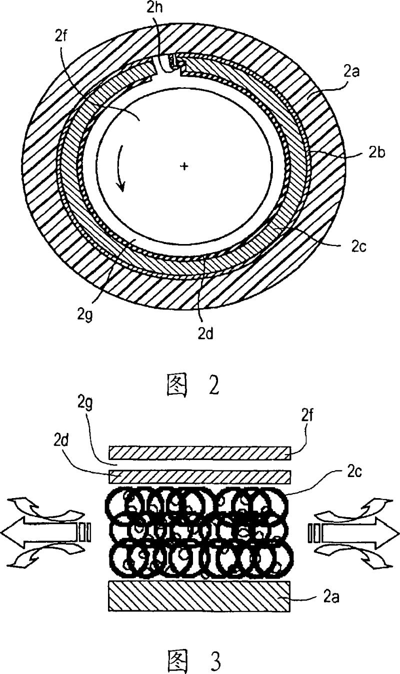
[0019] Figure 2 illustrates a cross-sectional view of an air foil bearing constructed in accordance with the present invention.

[0020] Referring to Fig. 2, the air foil bearing constructed according to the present invention includes: a bearing housing 2a, a top foil 2d, a porous foil 2c and a backing foil 2b.

[0021] The top foil 2d is arranged on the innermost side of the bearing housing 2a, positioned relative to the rotary shaft 2f, with an air lubricating film 2g in between. The upper surface of the top foil 2d facing the rotary shaft 2f is formed with a coated surface for body lubrication to minimize friction between it and the rotary shaft 2f during start and stop of the rotary shaft 2f. Those skilled in the art know that the purpose of this surface coating treatment is to increase the friction between the foils in an air foil bearin...


PUM


Abstract

There is provided an air foil bearing. The air foil bearing comprises a bearing housing and a first foil, wherein a first end of the first foil is fixed with respect to the bearing housing and a second end of the first foil is extended along a peripheral surface of a rotating shaft while maintaining a predetermined clearance with respect to the rotating shaft to thereby become a free end. The air foil bearing also comprises a second foil fabricated from a porous metallic material and extended along the first foil between the first foil and the bearing housing.

Description

technical field [0001] The present invention generally relates to an air foil bearing for supporting a rotating body in an air cycle machine (ACM), which is an integral part of an aircraft air conditioning system. More particularly, the present invention relates to an air foil bearing capable of further increasing the maximum rotational speed of a supported rotating body by using a foil composed of a porous metal material to improve its vibration damping capability. Background technique [0002] By utilizing the hydrodynamic properties of air as a lubricating medium, the film-like foil bears the axial load of the rotating shaft rotating at high speed. The high-speed rotating body may include an auxiliary power unit (APU) of the aircraft, an air conditioner (ACM) and the like. The structure of such foil journal bearings is generally similar to the structure of general air bearings. However, it differs in that a thin flexible foil (including a layer of corrugated foil) is em...

Claims


Application Information

Patent Timeline
Patent Type & Authority Applications(China)
IPC IPC(8): F16C27/02
CPCF16C2360/24F16C17/024F16C27/02F16C32/06
Inventor 李勇福金昌镐赵峻现柳根
Owner KOREA INST OF SCI & TECH
Why Eureka
Try Eureka