Head driving mechanism for flat knitting machine

A driving mechanism and technology of flat knitting machine, applied in knitting, weft knitting, textile and paper making, etc., can solve the problems of large volume, motor burnout, accidents, etc., to reduce the overall volume, save energy, and use safe Effect

Inactive Publication Date: 2007-10-03
常熟市国盛针织机械厂
View PDF0 Cites 8 Cited by
  • Summary
  • Abstract
  • Description
  • Claims
  • Application Information

AI Technical Summary

Problems solved by technology

The above-mentioned head drive mechanism mainly has the following deficiencies: one is that the motor 1 adopts an ordinary AC asynchronous motor, which has a large volume, a large temperature rise in the working process, easy heating, low power coefficient, and large energy consumption. It is necessary to install and use the above-mentioned motor 1. There are many transition parts, that is to say, a bridge needs to be passed between the motor 1 and the synchronous pulley 2, such as large and small pulleys, belts, large pulley shafts, and b

Method used


Image

  • Head driving mechanism for flat knitting machine
  • Head driving mechanism for flat knitting machine

Examples


Embodiment Construction

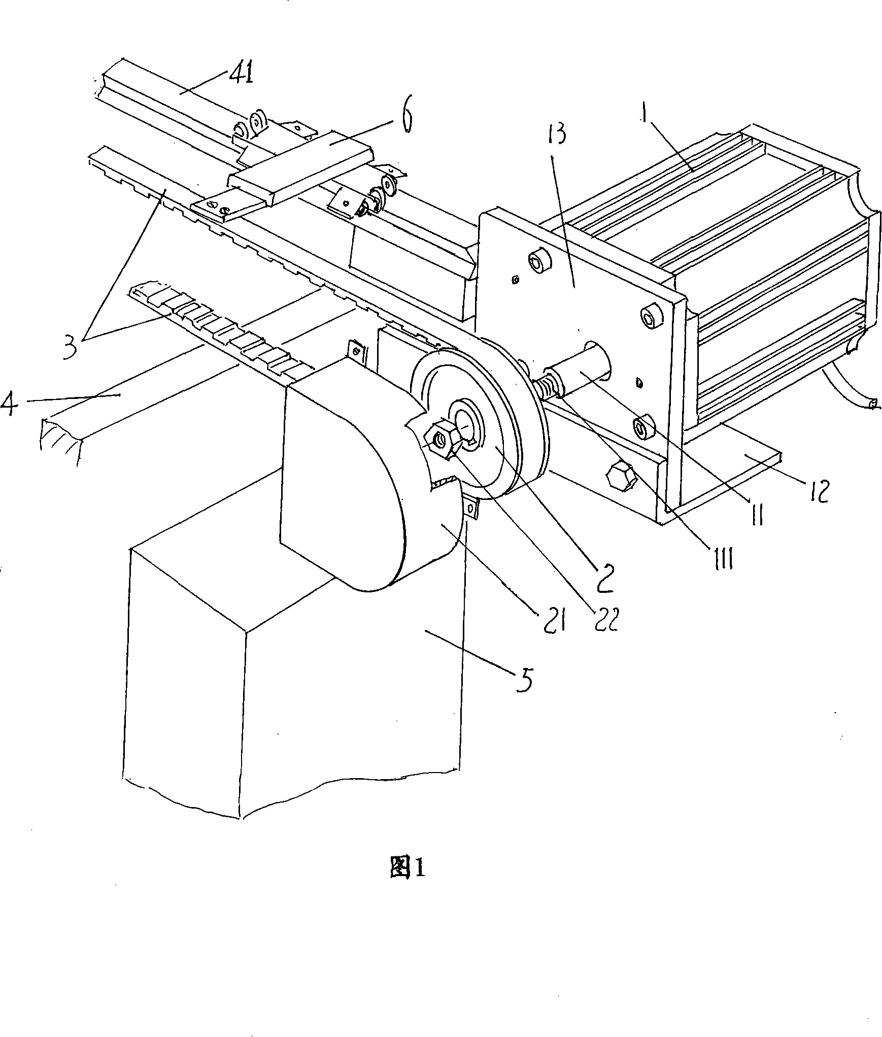
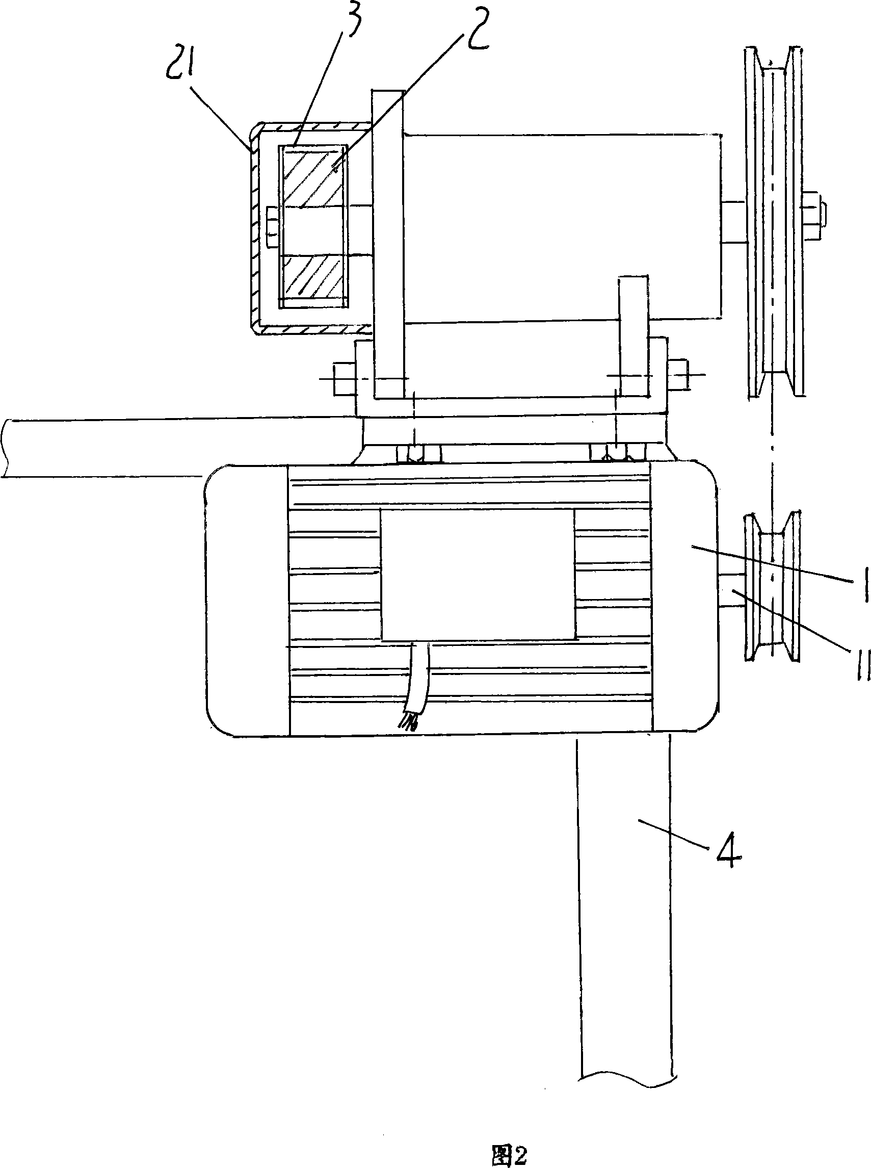
[0009] Please refer to Fig. 1, at an end of frame 4 promptly keep with the electric control box 5 same end installation motor 1 with the left end of current figure position, this motor 1 is installed on frame 4 by motor support 12. For the motor 1, a DC brushless motor should be used. This DC brushless motor can be obtained from market channels, for example, a DZGSWH-1 DC brushless motor produced and sold by Changshu Electric Machinery Factory Co., Ltd., Jiangsu Province, China. The end of the power output shaft 11 of the motor 1 is processed with a matching thread 111. After the timing pulley 2 is sleeved on the power output shaft 11, the timing pulley limiting nut 22 is screwed onto the matching thread 111. It is also possible to connect the synchronous pulley 2 and the power take-off shaft 11 with a flat key for fixed connection. A shield 21 is arranged outside the synchronous pulley 2, and the shield 21 is fixed with the motor holder 13 by screws, and the motor holder 13 i...


PUM


Abstract

The present invention is head driving mechanism for flat knitting machine, and belongs to the field of knitting machinery technology. The head driving mechanism includes a DC motor controlled with the electric control box, a synchronous belt wheel fixed directly onto the power output shaft of the motor, a synchronous belt on the synchronous belt wheel, and a pulley slip fitting the track on the frame. The present invention adopts DC motor, rather than asynchronous AC motor, and has the advantages of easy installation, small size, raised safety and low power consumption.

Description

technical field [0001] The invention relates to a head drive mechanism of a flat knitting machine, which is an improvement to the existing head drive mechanism of a flat knitting machine, and belongs to the technical field of knitting machinery. Background technique [0002] The structure of the head drive mechanism of the flat knitting machine in the prior art is shown in Figure 2, and the motor 1 controlled by the electric control box (not shown) is installed on the frame 4, and the power output shaft of the motor 1 Fix the small pulley on 11, the small pulley is connected with the big pulley through the belt (triangular belt), the big pulley is installed on one end of the big pulley shaft (the right end in the figure), the big pulley shaft is set on the bearing seat, and the bearing seat is set on the frame 4, at the other end (the left end of the figure) of the large pulley shaft, fix the synchronous pulley 2 covered by the shield 21, the synchronous belt 3 is sleeved on...

Claims


Application Information

Patent Timeline
IPC IPC(8): D04B15/96
Inventor 谭卫国
Owner 常熟市国盛针织机械厂
Why Eureka
Try Eureka