Design scheme of fast active control system for turbine vane tip interval

An active control system and blade tip clearance technology, applied in mechanical equipment, engine components, machines/engines, etc., can solve problems such as component deformation, achieve the effects of prolonging life, prolonging overhaul period, and improving reliability

Inactive Publication Date: 2007-10-03
岂兴明 +2
View PDF0 Cites 10 Cited by
  • Summary
  • Abstract
  • Description
  • Claims
  • Application Information

AI Technical Summary

Problems solved by technology

[0012] 2) Component deformati

Method used


Image

  • Design scheme of fast active control system for turbine vane tip interval
  • Design scheme of fast active control system for turbine vane tip interval
  • Design scheme of fast active control system for turbine vane tip interval

Examples


Embodiment Construction

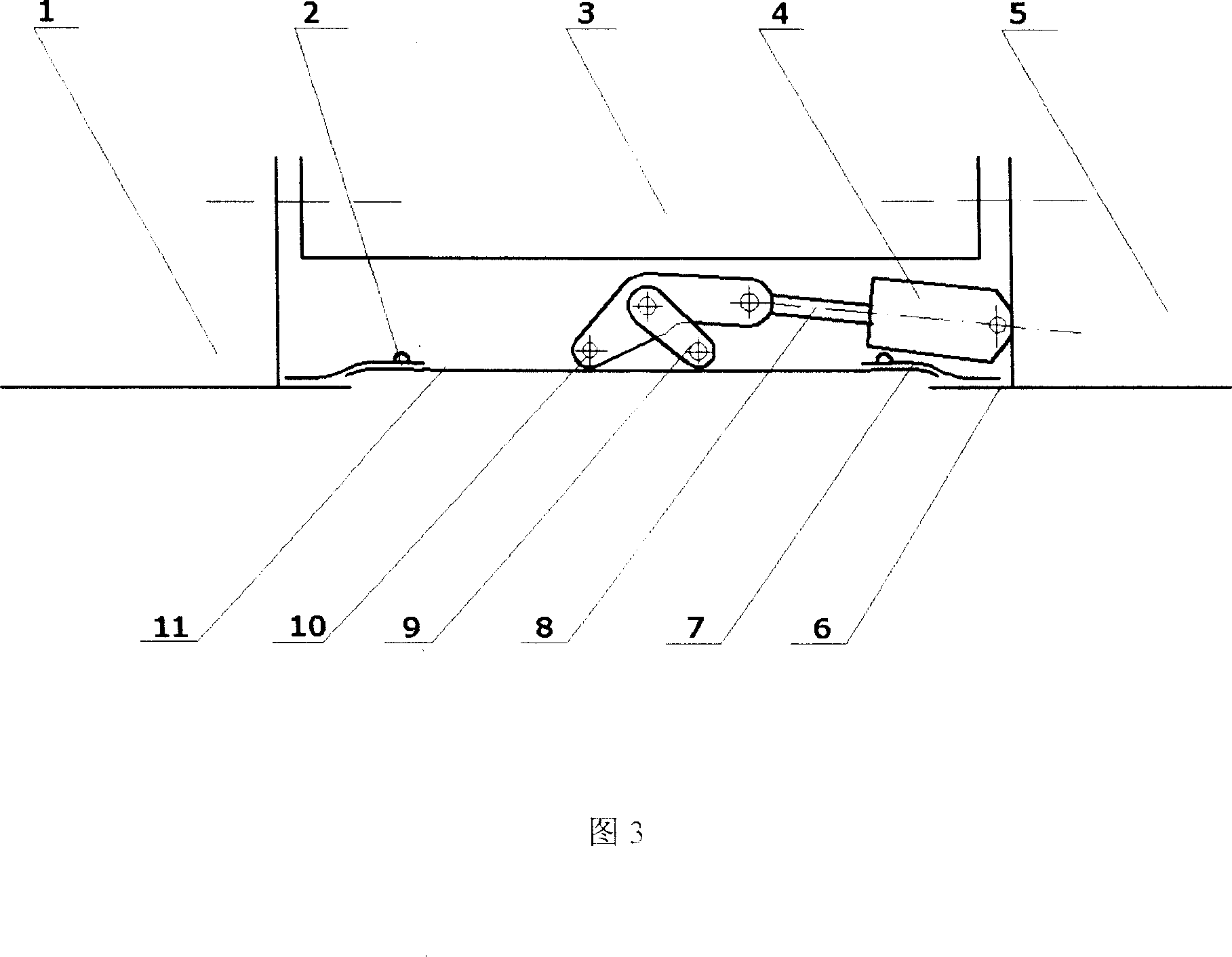
[0041] Appropriately modifying and redesigning the mature aero-engine variable tail nozzle control technology and applying it to the rapid active control system of the turbine blade tip clearance can reduce technical risks and development costs. At the same time, the temperature of the flow field at the tail nozzle is also above 1000K, which is similar to the temperature of the flow field of the turbine, and the use of efficient cooling system materials and structural changes are also reduced accordingly. Therefore, the feasibility of this scheme can be verified on the active control of the turbine blade tip of the steam turbine. Improvements in materials and cooling systems were then made for ground and marine gas turbines. After the size and weight requirements of the aero-engine are met, it is applied to the rapid tip clearance active control of the aero-engine turbine.


PUM


Abstract

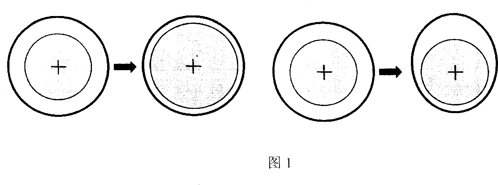
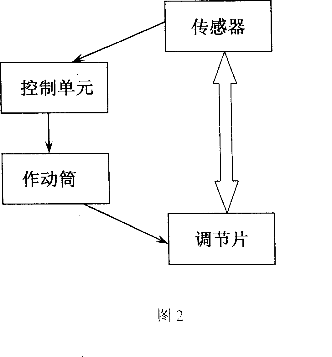
The present invention is one design scheme of fast active control system for the vane tip interval of aviation engine, and features the mechanical executing mechanism. The mechanical executing mechanism is designed by referring variable cross section tailing spout controlling technology for aviation engine and applied in the fast active control system of turbine vane tip interval. Compared with the control system designed based on traditional heat responding method, the fast active control system of turbine vane tip interval has the advantages of fast response speed, high economical efficiency, asymmetrical deformation, high reliability and long service life. The fast active control system of turbine vane tip interval consists of five parts: turbine casing, regulating sheet and sealing sheet, regulating unit, connecting section and control unit.

Description

1. Technical field [0001] Active control of tip clearance is a common concern in turbomachinery. The main performance indicators such as the efficiency and fuel consumption rate of aeroengines, ground gas turbines, marine gas turbines, steam turbines and other engineering machinery are all affected by the blade tip clearance. 2. Background technology [0002] 2.1 Research background and significance [0003] The turbine is an important part of the airflow that converts extremely high enthalpy into kinetic energy. The efficiency of the turbo affects the overall engine performance. With the continuous pursuit of high pressure ratio, high aerodynamic load, high efficiency and low aspect ratio blades, the rotor blades must bear more loads, and the most serious loss occurs in the tip area of ​​the blades. A large number of experimental studies have shown that most axial flow compressors first stall at the blade tip. In civil and aviation axial flow compressors, the interaction...

Claims


Application Information

Patent Timeline
IPC IPC(8): F01D11/16
Inventor 岂兴明
Owner 岂兴明
Why Eureka
Try Eureka