Residual dispersion real-time detection system and method

A residual dispersion and real-time detection technology, which is applied in transmission systems, wavelength division multiplexing systems, electromagnetic wave transmission systems, etc., can solve the problems that the residual dispersion test cannot be detected in real time, and achieve the effect of improving the test level

Inactive Publication Date: 2007-10-03
ZTE CORP
View PDF0 Cites 3 Cited by
  • Summary
  • Abstract
  • Description
  • Claims
  • Application Information

AI Technical Summary

Problems solved by technology

[0005] The technical problem to be solved by the present invention is to propose a real-time residual dispersion detection system and method for the problem that the existing wavelength division multiplexing optical transmission system residual dispersion test cannot be detected in real time

Method used


Image

  • Residual dispersion real-time detection system and method
  • Residual dispersion real-time detection system and method
  • Residual dispersion real-time detection system and method

Examples


Embodiment Construction

[0032] Embodiments of the present invention will be further described in detail below in conjunction with the accompanying drawings.

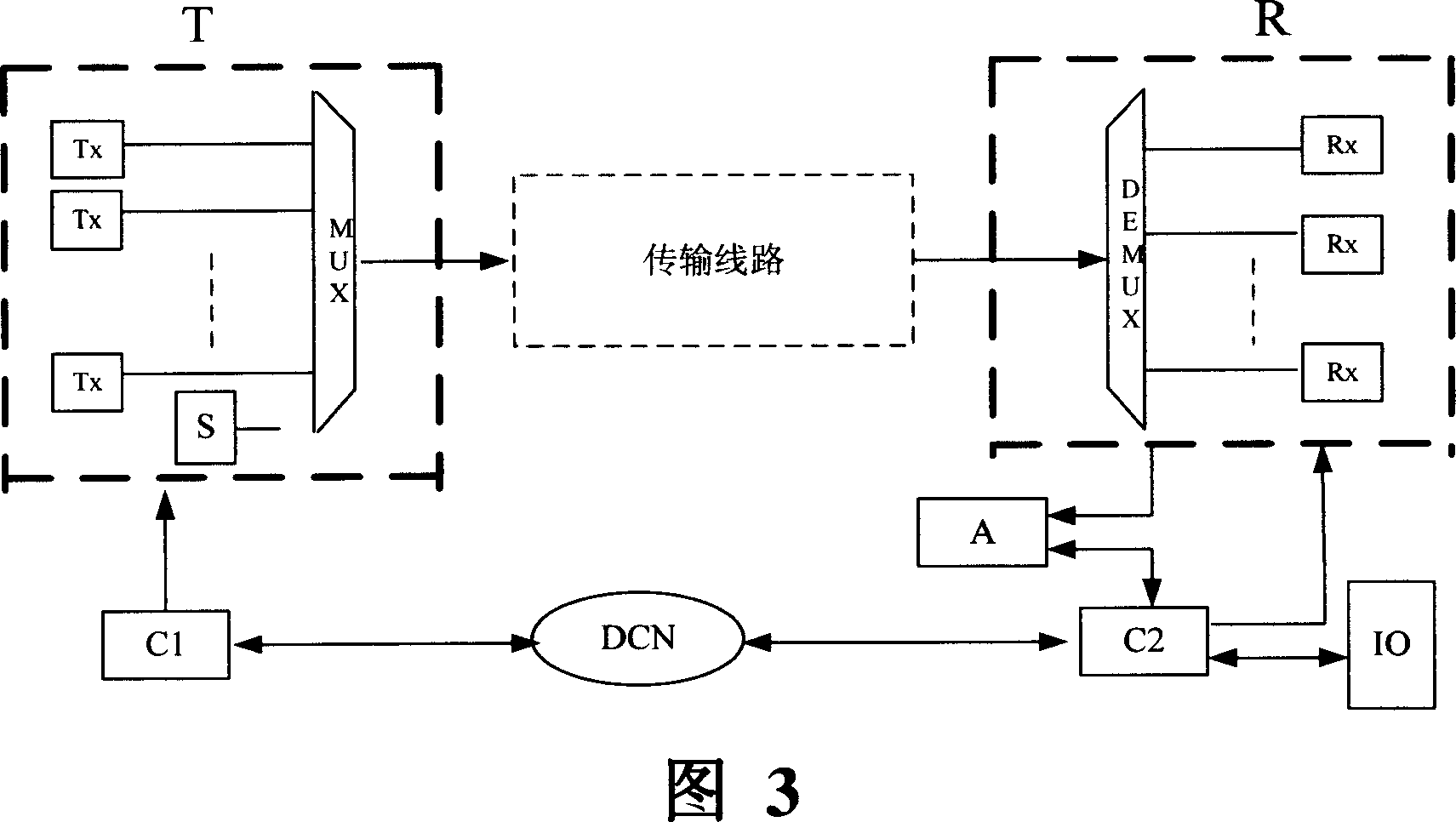
[0033] The residual dispersion real-time detection system of the present invention, as shown in Figure 3, the system includes a sending device T located at the system sending end, which is composed of an optical sending part and a multiplexer MUX; a transmission line for transmitting signals; The receiving device R at the end is composed of a demultiplexer DEMUX and an optical receiving part. And, the control device C1 at the sending end, the dispersion test source S, the control device C2 at the receiving end, the dispersion detection processing unit A at the receiving end, and the information interaction interface IO.

[0034] Among them, the control device C1 at the sending end and the control device C2 at the receiving end communicate through a data signaling transmission network (DCN) to perform cooperative operations; the control device C...


PUM


Abstract

A real-time detection system of residual dispersion comprises dispersion test source for outputting test wavelength, dispersion detection-processing unit for carrying out residual dispersion detection on outputted test wavelength, sending end control unit for controlling said test source to output test wavelength, receiving end control unit for sending trigger condition to start up residual dispersion detection and for controlling said detection-processing unit to carry out residual dispersion detection on output of dispersion test source.

Description

technical field [0001] The invention relates to a system and method for real-time detection of residual dispersion in wavelength division multiplexing (WDM) optical transmission, in particular to dispersion control in the field of high-speed optical signal transmission. Background technique [0002] The dispersion of the optical fiber is one of the reasons for the waveform distortion generated after the optical signal is transmitted through the optical fiber. Since different frequency components or different modes of the optical signal have different transmission speeds in the optical fiber, different frequency components in the optical signal arrive at the end of the optical fiber first and then later, resulting in waveform distortion. This kind of distortion is manifested in the transmission of a pulse signal. As the transmission distance of the light pulse increases, the width of the pulse becomes wider and wider, which requires management and compensation for dispersion....

Claims


Application Information

Patent Timeline
Patent Type & Authority Applications(China)
IPC IPC(8): H04B10/08H04B10/18H04J14/02H04B10/077
Inventor 苏婕王加莹
Owner ZTE CORP
Why Eureka
Try Eureka