A graphical modeling device and method for an automated test system

A technology for automated testing and graphical modeling, applied in program control devices, electrical testing/monitoring, etc., can solve the problems of increasing complexity of the equipment under test, insufficiency, and difficulty in clearly grasping and managing models, achieving intuitive and efficient automation Test system modeling, reduce design difficulty and workload, and improve the effect of automated testing

Active Publication Date: 2017-07-28
SHANDONG UNIV OF SCI & TECH
View PDF5 Cites 0 Cited by
  • Summary
  • Abstract
  • Description
  • Claims
  • Application Information

AI Technical Summary

Problems solved by technology

[0003]With the emergence of new products, the complexity of the device under test is also continuously increasing, which leads to a dramatic increase in the number of test points that must be connected to the device under test
The sharp increase in the number of test points not only means a sharp increase in the complexity of test instruments, switching systems and test connectors in the automated test system, but also increases the complexity of the signal communication path in the automated test system
[0004] At the initial stage of design, the current automated test system relies on manual experience to design the equipment composition and signal relationship in the automated test system, and manually records and optimizes it. The manual recording method cannot allow other testers to quickly understand the composition of the system, and when the system is large in scale and complex in structure, the model will be difficult to grasp and manage clearly, and it will not be possible for testers to perform automatic testing in a WYSIWYG manner. The model of the system is designed and optimized, and the knowledge of the design method recorded manually cannot be used by the automated test system during the automated test process, and cannot meet the requirements for improving the degree of automated execution in the future

Method used


Image

  • A graphical modeling device and method for an automated test system
  • A graphical modeling device and method for an automated test system
  • A graphical modeling device and method for an automated test system

Examples


Embodiment 1

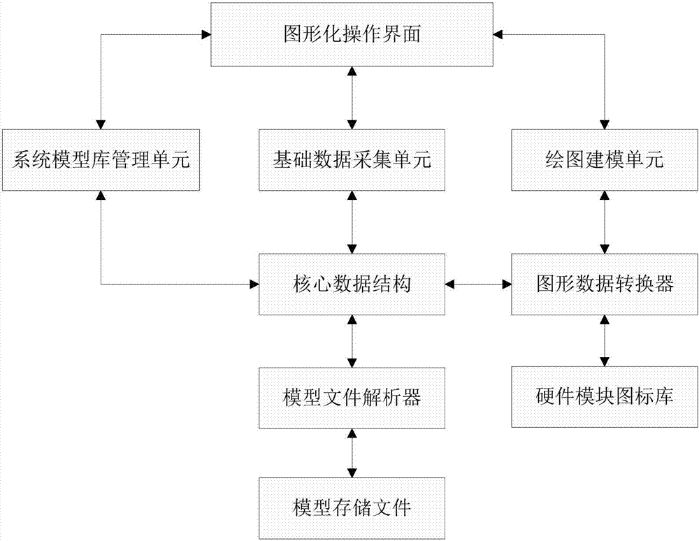
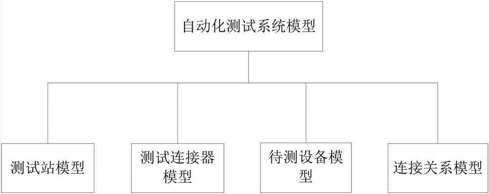
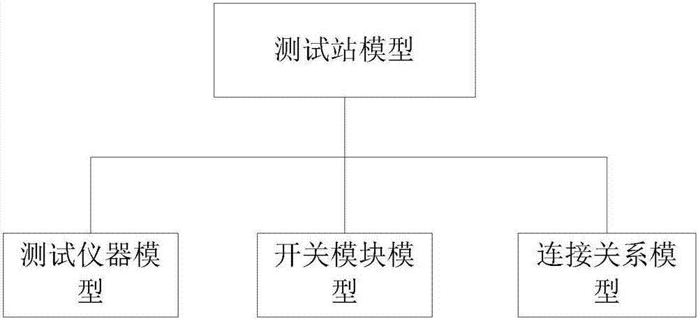
[0048] Such as Figure 1-Figure 3 As shown, a graphical modeling device for an automated test system is used to build an automated test system model, including a graphical operation interface, a system model library management unit, a basic data acquisition unit, a drawing modeling unit, a graphic data conversion unit, a core Data structure, model file parser, model storage file and hardware module icon library;

[0049] The graphical operation interface includes an area for receiving user management instructions, a system module library management area, a module attribute configuration area, and an automated test system module and a connection relationship drawing area, wherein: the system module library management area includes several components that constitute automation Test the hardware modules of the system, and can provide any one or more functions of adding, modifying, and deleting the system modules; the module attribute configuration area is used to configure the at...


PUM


Abstract

The invention relates to a graphical modeling device and method for an automated test system, belonging to the field of automated testing, including: a graphical operation interface, a system model library management unit, a basic data acquisition unit, a drawing modeling unit, a graphic data conversion unit, Core data structure, model file parser, model storage file and hardware module icon library, the invention allows users to design and optimize the model composition and signal path scheme of the automated test system in a graphical way before building the physical automated test system, and realize The intuitive and efficient automated test system simulation design reduces development costs and improves development efficiency, and stores model data in a formatted manner to provide support for the execution of automated tests.

Description

technical field [0001] The invention relates to a graphical modeling device and method for an automatic testing system, which is related to the modeling technology of a computer information system and the computer image data processing technology, and belongs to the technical field of automatic testing. Background technique [0002] An automated test system refers to a system that automatically measures the device under test, processes the data, and displays or outputs the test results in an appropriate manner with little or no human participation. Compared with manual testing, automated testing saves time and effort, and can improve labor productivity and product quality. The hardware composition of an automated test system usually includes test instruments, switching systems, main control computers, test connectors, and equipment to be tested. Connect the device to the device under test, apply an excitation signal to the device under test, and measure the output signal of...

Claims


Application Information

Patent Timeline
Patent Type & Authority Patents(China)
IPC IPC(8): G06F9/44G05B23/02
Inventor 郭素敏吴晓辰徐克宝苏春建李洪宇戴向云
Owner SHANDONG UNIV OF SCI & TECH
Why Eureka
Try Eureka