Single phase gas insulation switch device

A gas-insulated switch and equipment technology, which is applied in the setting of switchgear, switchgear, electrical components, etc., can solve the problems of being easily limited by external natural conditions, unable to make full use of land resources, and difficult to ensure normal operation, etc. To achieve the effect of reducing the volume, making full use of land resources, and reducing the floor space

Active Publication Date: 2007-10-10
TAIPINGYANG POWER EQUIP GROUP CHANGZHOU
View PDF0 Cites 5 Cited by
  • Summary
  • Abstract
  • Description
  • Claims
  • Application Information

AI Technical Summary

Problems solved by technology

[0002] At present, the conventional switchgear usually adopts air insulation, and its disadvantage is that the electrical gap is relatively large, resulting in a large volume of the entire cabinet and a large footprint, so that land resources cannot be fully utilized.
In addition, the entire switch system is not completely enclosed in a sealed box, which is easily restricted by external natural conditions, and it is difficult to ensure normal operation in harsh weather conditions

Method used


Image

  • Single phase gas insulation switch device
  • Single phase gas insulation switch device
  • Single phase gas insulation switch device

Examples


Embodiment Construction

[0016] The present invention will be described in further detail below in conjunction with the accompanying drawings and embodiments.

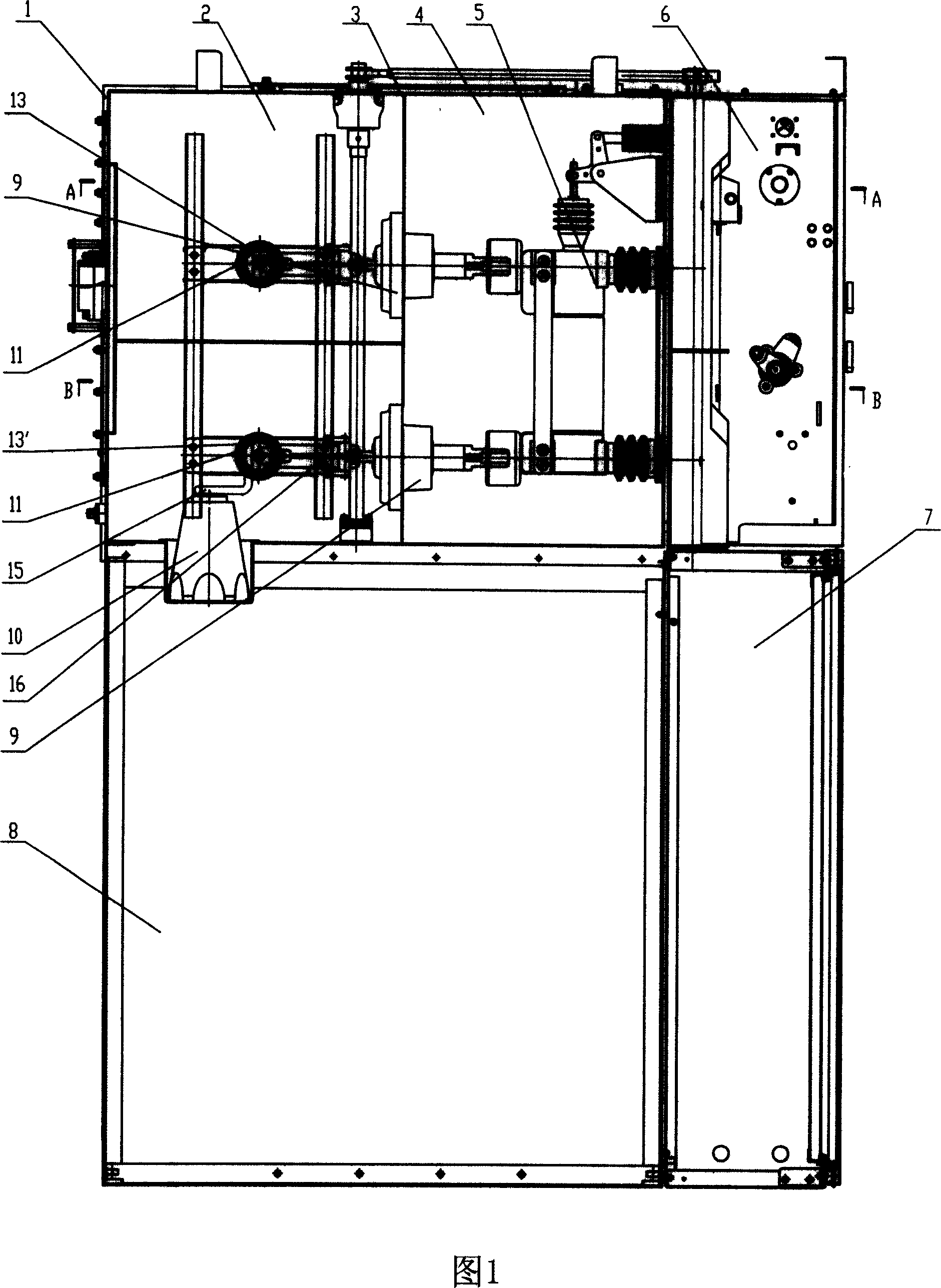
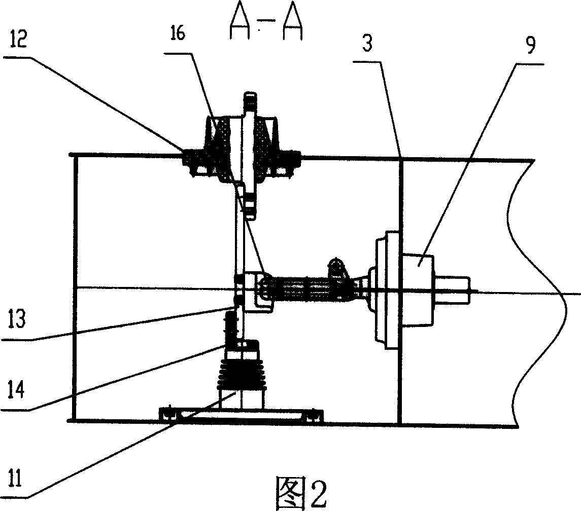
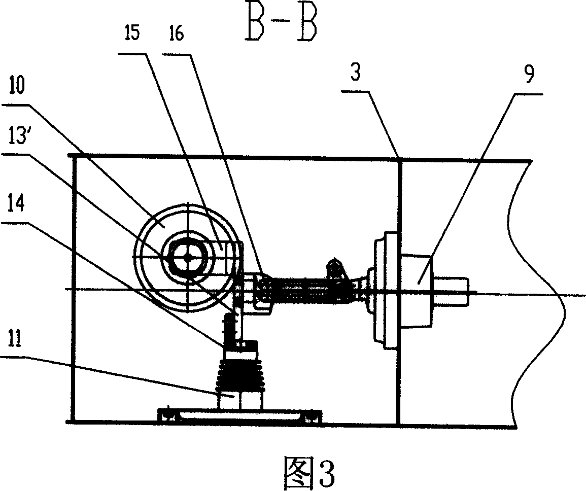
[0017] As shown in Figures 1 to 9, a single-phase gas-insulated switchgear is composed of a box body 1, a cable room 8, an instrument room 7, a circuit breaker 5, and an operating mechanism 6. The operating mechanism 6 is located on the outer surface of the box body 1. For the control of the switch, the box body 1 sits on the cable room 8 and is fixedly connected to the top of the cable room 8 by screws. The inner cavity of the box body 1 is divided into a relatively sealed bus room 2 and a circuit breaker room 4 by a partition plate 3. Busbar chamber 2 is provided with busbar connector 12, insulator 11, upper busbar 13, lower busbar 13', connecting bar 15, connecting block 14 and socket 10, one end of upper busbar 13 is connected with busbar connector 12, and the other end is connected by The block 14 is connected to the insulator 11, one end...


PUM


Abstract

The isolating switchgear is composed of cabinet, cable room, instrument room, breaker, and operating mechanism. The operating mechanism is located on external surface of cabinet. Cabinet seat is on the cable room. Clapboard divides cavity inside cabinet into relative sealed busbar room, and breaker room. Busbar connector, insulator, busbar connection row, connecting block, and socket are setup in busbar room. Breaker is fixed to inner wall of cabinet. Being installed on clapboard, busbar connector is composed of insulating sleeve and current conducting rod (CCR). The current conducting rod passes through the insulating sleeve. Gas insulation dielectric is contained inside the busbar room and the breaker room. Being installed in busbar room, isolation knife is composed of movable knife, static knife, and connecting plate. Through rivet, the connecting plate is hinge jointed to CCR. Features are: good insulatibity, small electric gap, and normal operation under extreme climate.

Description

technical field [0001] The invention relates to the field of switchgear, in particular to a single-phase gas-insulated switchgear, which is mainly used in electrified railways. Background technique [0002] At present, the conventional switchgear is usually air-insulated, and its disadvantage is that the electrical gap is relatively large, resulting in a large volume of the entire cabinet and a large footprint, so that land resources cannot be fully utilized. In addition, the entire switching system is not completely enclosed in a sealed box, which is easily restricted by external natural conditions, and it is difficult to ensure normal operation under harsh weather conditions. Contents of the invention [0003] The purpose of the present invention is to overcome the deficiencies of the prior art and provide a single-phase gas insulated switchgear with good insulation performance, small electric gap, and normal operation under harsh weather conditions. [0004] The techni...

Claims


Application Information

Patent Timeline
Patent Type & Authority Applications(China)
IPC IPC(8): H02B13/035H02B1/20
Inventor 霍曙琴黄协平吴耀文蒋菊仙刘俊才
Owner TAIPINGYANG POWER EQUIP GROUP CHANGZHOU
Why Eureka
Try Eureka