Method and device for measuring jet thrust

A measuring device, thrust direction technology, applied in measuring devices, force/torque/work measuring instruments, instruments, etc., can solve the problems of high debugging and calibration requirements, measurement errors, etc., to achieve strong comparability, good repeatability, The effect of processing with reasonable size

Inactive Publication Date: 2007-10-17
INST OF MECHANICS - CHINESE ACAD OF SCI
View PDF0 Cites 27 Cited by
  • Summary
  • Abstract
  • Description
  • Claims
  • Application Information

AI Technical Summary

Problems solved by technology

[0004] The purpose of the present invention is to overcome the defect that the existing force measurement principle requires high debugging and calibration when meas

Method used


Image

  • Method and device for measuring jet thrust
  • Method and device for measuring jet thrust
  • Method and device for measuring jet thrust

Examples


Embodiment 1

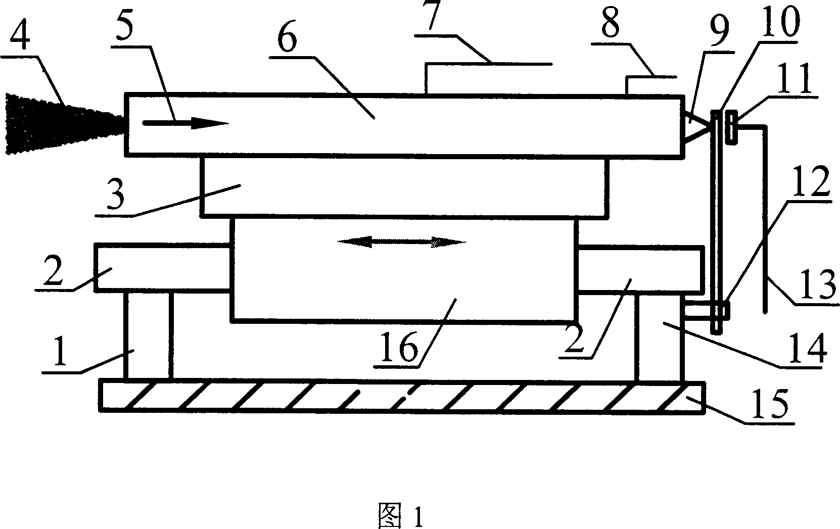
[0027] With reference to Fig. 1, make a measuring device of jet thrust of the present invention. The first bracket 1 and the second bracket 14 are fixed on the base 15 , and the top ends of the first bracket 1 and the second bracket 14 support a guide mechanism 2 . The bearing set 16 and the guide mechanism 2 form a kinematic pair, the support base 3 and the bearing set 16 are fixed together, and the thruster 6 whose thrust is to be measured is fixed on the support base 3, so as to realize the fixation with the bearing set 16. The support base 3 is made of a material with good heat insulation.

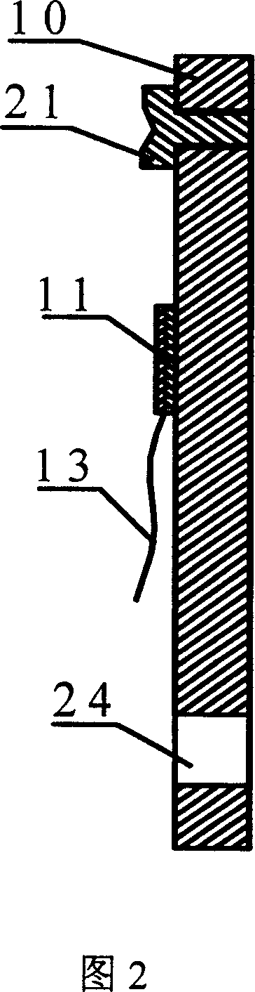
[0028] As shown in Figure 2, a metal strip is used as the cantilever beam 10, and one end of the cantilever beam 10 of the metal strip has a positioning hole 24, and the fastener 12 fixes the cantilever beam 10 on the second support 14 through the positioning hole 24, also It can be fixed on the first bracket 1, and the fastener 12 can be fixed on different positions on the bracket, s...

Embodiment 2

[0031] As shown in Figure 1, make a jet thrust measuring device of the present invention. A base 15 is made, on which the first support 1 and the second support 14 are fixed, and the top ends of the first support 1 and the second support 14 support the guide mechanism 2 . The bearing set 16 and the guide mechanism 2 form a kinematic pair, the support base 3 and the bearing set 16 are fixed together, and the thruster 6 whose thrust is measured is fixed on the support base 3 by screws, so as to realize the fixation with the bearing set 16 . The support base 3 is made of a material with good heat insulation. As shown in Figure 2, a positioning hole 24 is arranged on one end of the cantilever beam 10, and the fastener 12 fixes the cantilever beam 10 on the second bracket 14 through the positioning hole 24, and the fastener 12 can be fixed to different parts of the second bracket 14. Position, measured in thrust for thrusters of different sizes. There is a sensor 11 near the susp...

Embodiment 3

[0034] Fig. 4 is the static calibration schematic diagram of the measuring device of jet thrust of the present invention, and the center of thruster 6 forms aperture, and 200 micron diameter optical fiber 37 one ends are fixedly connected in thruster nozzle, and the other end runs through aperture and electric thrust thruster 6 Axle hole, and pass through from top 9, cantilever beam 10, ride on precision bearing 38 at last. The center of the precision bearing 38 is fixed on the shaft 39, and the shaft 39 is fixed on the base 15 of the measuring device. The end of the optical fiber close to the precision bearing 38 is installed with a detachable weight 40, and the same thrust as the gravity of the weight 40 is as follows: Arrow 5 acts on the cantilever beam 10 , and the sensor 11 detects the force acting on the cantilever beam 10 . The jet thrust measuring device of the present invention can be calibrated by comparing the force measured by the sensor with the gravity of the wei...


PUM


Abstract

The invention relates to a device for measuring jet thrust which includes a guiding mechanism supported by a first bracket mounted on the base and a second bracket, and provided with a bearings group which is fixed together with the support base having a thruster of measured thrust disposed by screws thereon; A trust measurement mechanism comprising a socle girder opened an aligning hole on one end and fixed on the bracket by a fastener through the aligning hole, the top end of which is suspended and higher than the support base, a sensor adhibited on the surface of the suspension girder is electrically connected with acquisition, process and display system outside through signal lines. The measurement device for the invention is independent of operational sensation of mounting and debugging persons, so as to guaranty repetitive calibration and reproducibility of experiment measurement result, and good comparability of thrust measurement result for different operating parameters.

Description

technical field [0001] The invention relates to a jet thrust measurement method and a device thereof, in particular to a jet thrust measurement method and a device thereof for on-orbit spacecraft attitude control and orbit control. Background technique [0002] With the development of the times, the space control capability plays an increasingly crucial role in the security and development of a country. Chemical propellants are suitable for short-duration, high-thrust propulsion missions. Relatively speaking, electric rocket propulsion technology can obtain higher carrying efficiency, and is suitable for propulsion tasks with long-term, small and medium thrust, and high specific impulse. At present, for various purposes of satellites or spacecraft, in order to reduce weight and size, improve positioning accuracy, and extend operating life, the use of space electric propulsion technology has become an indispensable and effective way. Whether it is the development of the nat...

Claims


Application Information

Patent Timeline
IPC IPC(8): G01L5/00
Inventor 潘文霞吴承康李腾
Owner INST OF MECHANICS - CHINESE ACAD OF SCI
Why Eureka
Try Eureka