Method and device for measuring jet thrust
A measuring device, thrust direction technology, applied in measuring devices, force/torque/work measuring instruments, instruments, etc., can solve the problems of measurement error, debugging and calibration requirements, and achieve good repeatability, strong comparability, and processing. Matching size is reasonable
- Summary
- Abstract
- Description
- Claims
- Application Information
AI Technical Summary
Problems solved by technology
Method used
Image
Examples
Embodiment 1
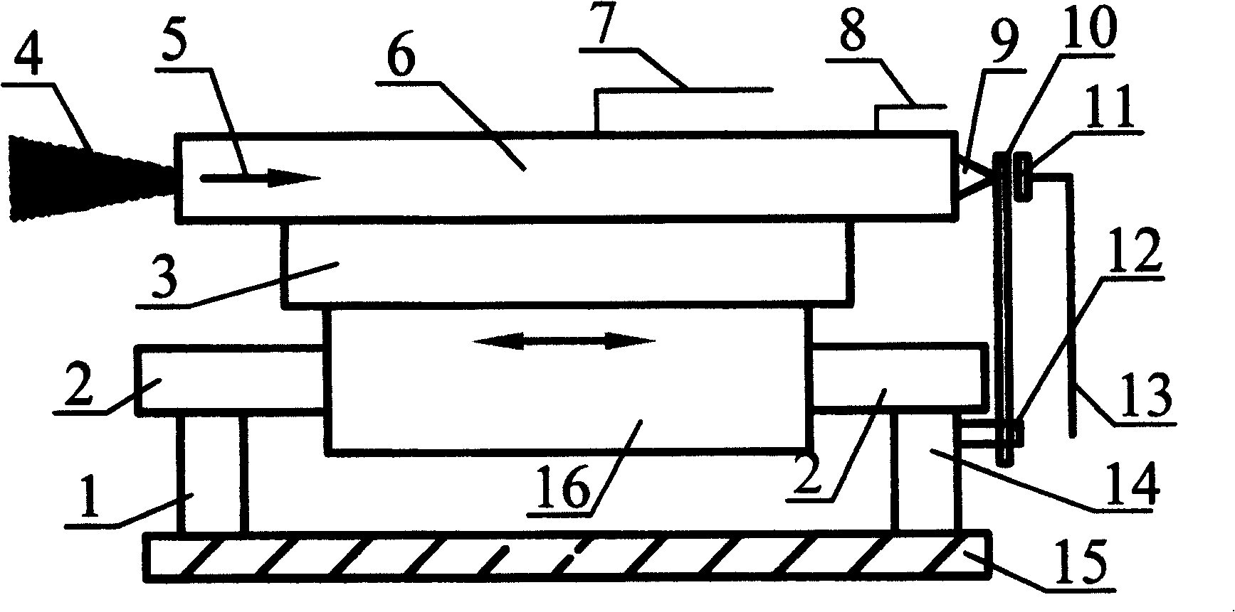
[0027] refer to figure 1 , make a measuring device of jet thrust of the present invention. The first bracket 1 and the second bracket 14 are fixed on the base 15 , and the top ends of the first bracket 1 and the second bracket 14 support a guide mechanism 2 . The bearing set 16 and the guide mechanism 2 form a kinematic pair, the support base 3 and the bearing set 16 are fixed together, and the thruster 6 whose thrust is to be measured is fixed on the support base 3, so as to realize the fixation with the bearing set 16. The support base 3 is made of a material with good heat insulation.
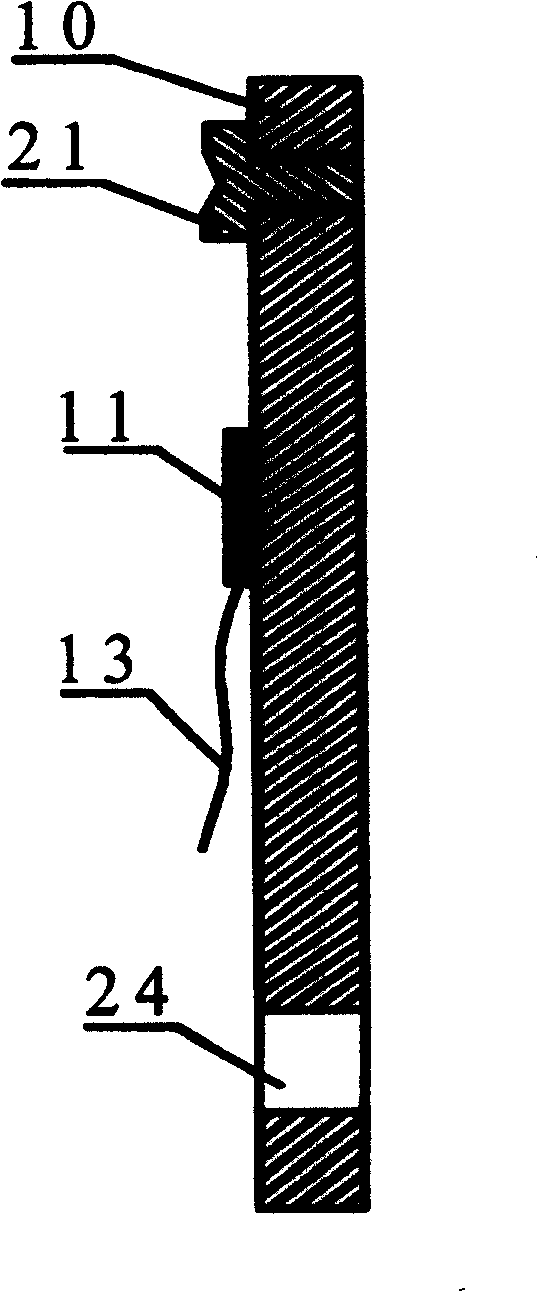
[0028] Such as figure 2 As shown, a metal strip is used as the cantilever beam 10, and one end of the cantilever beam 10 of the metal strip has a positioning hole 24, and the fastener 12 fixes the cantilever beam 10 on the second support 14 through the positioning hole 24, and can also be fixed on On the first bracket 1 , the fasteners 12 can be fixed at different positions on the bracke...
Embodiment 2
[0031] Such as figure 1 Shown, make a measuring device of jet thrust of the present invention. A base 15 is made, on which the first support 1 and the second support 14 are fixed, and the top ends of the first support 1 and the second support 14 support the guide mechanism 2 . The bearing set 16 and the guide mechanism 2 form a kinematic pair, the support base 3 and the bearing set 16 are fixed together, and the thruster 6 whose thrust is measured is fixed on the support base 3 by screws, so as to realize the fixation with the bearing set 16 . The support base 3 is made of a material with good heat insulation. Such as figure 2 As shown, a positioning hole 24 is arranged on one end of the cantilever beam 10, and the fastener 12 fixes the cantilever beam 10 on the second bracket 14 through the positioning hole 24, and the fastener 12 can be fixed at different positions of the second bracket 14, so as to Suitable for thrust measurement of thrusters of different sizes. There ...
Embodiment 3
[0034] Figure 4 It is the static calibration schematic diagram of the measuring device of jet thrust of the present invention, and the center of thruster 6 forms small hole, and one end of 200 micron diameter optical fiber 37 is fixedly connected at the nozzle of thruster, and the other end runs through the central axis of small hole and electric thruster 6 hole, and from the top 9, through the cantilever beam 10, and finally ride on the precision bearing 38. The center of the precision bearing 38 is fixed on the shaft 39, and the shaft 39 is fixed on the base 15 of the measuring device. The end of the optical fiber close to the precision bearing 38 is installed with a detachable weight 40, and the same thrust as the gravity of the weight 40 is as follows: Arrow 5 acts on the cantilever beam 10 , and the sensor 11 detects the force acting on the cantilever beam 10 . The jet thrust measuring device of the present invention can be calibrated by comparing the force measured by ...
PUM
 Abstract
Description
Claims
Application Information
 - R&D
- Intellectual Property
- Life Sciences
- Materials
- Tech Scout
- Unparalleled Data Quality
- Higher Quality Content
- 60% Fewer Hallucinations
Browse by: Latest US Patents, China's latest patents, Technical Efficacy Thesaurus, Application Domain, Technology Topic, Popular Technical Reports.
© 2025 PatSnap. All rights reserved.Legal|Privacy policy|Modern Slavery Act Transparency Statement|Sitemap|About US| Contact US: help@patsnap.com


