

Endoscope shape detection device
A detection device, endoscope technology, applied in the direction of surgery, etc., can solve the actual inspection obstacles, the position and insertion shape of the front end of the endoscope shape detection device cannot be obtained, etc.
- Summary
- Abstract
- Description
- Claims
- Application Information
AI Technical Summary
Problems solved by technology
Method used
Image

Examples
Embodiment 1
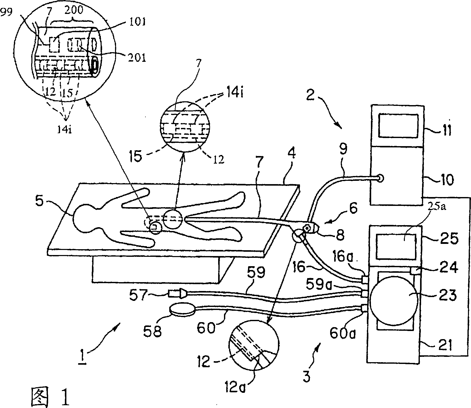
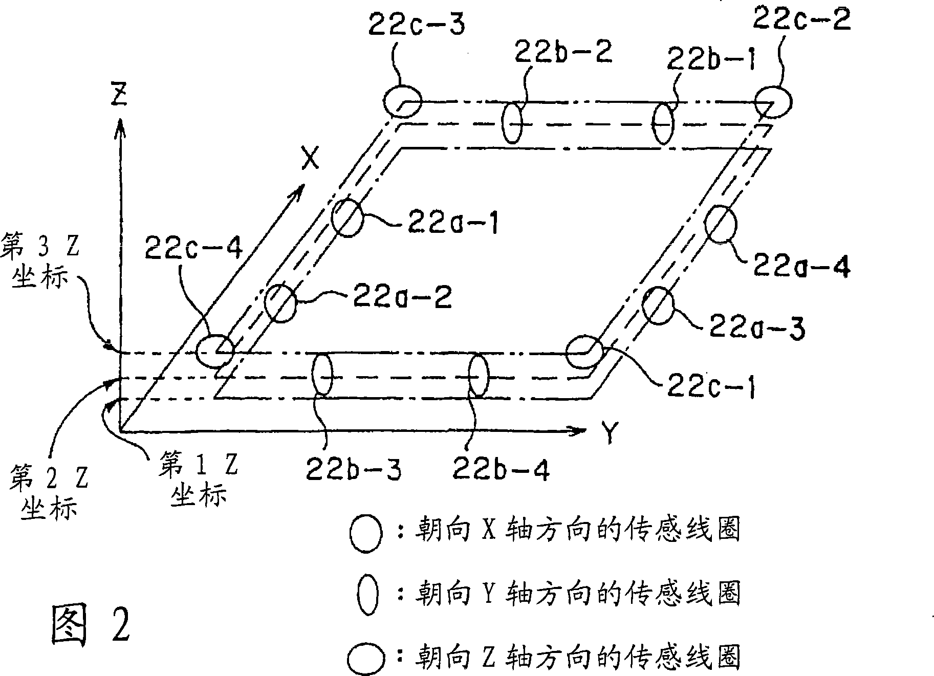
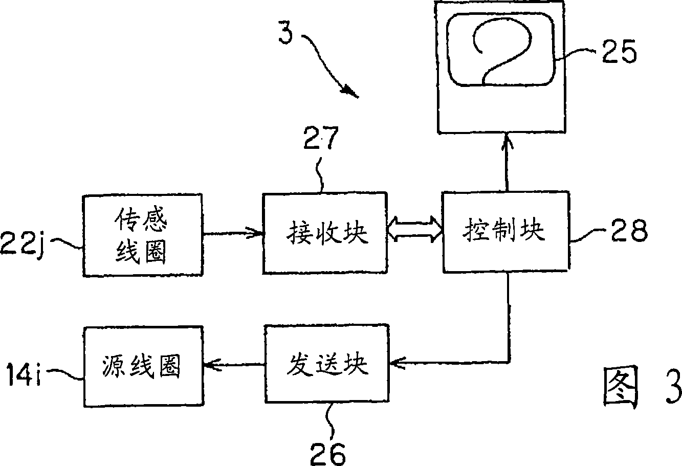
[0045] FIGS. 1 to 17 relate to Embodiment 1 of the present invention. FIG. 1 is a configuration diagram showing the structure of an endoscope system, and FIG. 2 is a diagram showing an example of the arrangement of coils built in the coil unit of FIG. 3 is a structural diagram showing the structure of the endoscope shape detection device of FIG. 1, FIG. 4 is a diagram showing the structure of the receiving block and the control block of FIG. 3, and FIG. 5 is a detailed structure of the receiving block of FIG. Fig. 6 is a timing chart showing the operation of the two-port memory of Fig. 4, Fig. 7 is a diagram showing the structure of the electronic endoscope of Fig. 1, and Fig. 8 is a diagram showing the two-port memory of Fig. 4 Fig. 9 is a diagram showing the structure of the source coil drive circuit section of Fig. 4, Fig. 10 is a flowchart explaining the operation of the endoscope system of Fig. 3, and Fig. 11 is a diagram showing the configuration of the endoscope system of F...
Embodiment 2
[0108] 18 to 20 relate to Embodiment 2 of the present invention. FIG. 18 is a diagram showing the structure of the source coil drive circuit of the endoscope shape detection device. FIG. 19 is a diagram showing the memory map of the two-port memory. 20 is a flowchart explaining the function of the endoscope system.
[0109] Since the second embodiment is almost the same as the first embodiment, only the different points will be described, and the same reference numerals will be attached to the same structure, and the description will be omitted.
[0110] In this embodiment, as shown in FIG. 18, the source coil drive circuit section 31 of the endoscope shape detection device 3 is configured to have a plurality of source coils 14i: an oscillator 110, an amplifier 111, and a measurement flow into the source coil 14i. The current detecting unit 114 for the alternating current inside, the voltage detecting unit 115 for measuring the alternating voltage applied to the source coil 14i, a...
Embodiment 3
[0124] Figures 21 to 25 relate to Embodiment 3 of the present invention. Figure 21 is a diagram showing the configuration of the source coil drive circuit section of the endoscope shape detection device, and Figure 22 is a flowchart illustrating the function of the endoscope system 23 is an explanatory diagram for explaining the processing of FIG. 22, FIG. 24 is a diagram showing a configuration of a modification of the source coil drive circuit section of FIG. 21, and FIG. 25 is an effect on the source coil drive circuit section of FIG. 24 An explanatory diagram for explanation.
[0125] Since the third embodiment is almost the same as the second embodiment, only the different points will be described, and the same reference numerals will be attached to the same structure, and the description will be omitted.
[0126] In this embodiment, as shown in FIG. 21, the CPU 32 is configured to control the output voltage value of the oscillator 110 based on the impedance Z of the source c...
PUM
 Abstract
Description
Claims
Application Information