Medical examination apparatus

A technology for inspecting equipment and equipment, applied in medical science, adjusting magnetic variables, sensors, etc., can solve problems such as anxiety and patient discomfort

Inactive Publication Date: 2007-10-17
KONINKLIJKE PHILIPS ELECTRONICS NV
View PDF1 Cites 10 Cited by
  • Summary
  • Abstract
  • Description
  • Claims
  • Application Information

AI Technical Summary

Problems solved by technology

However, the limited space provided in the cavi...

Method used


Image

  • Medical examination apparatus
  • Medical examination apparatus
  • Medical examination apparatus

Examples


Embodiment Construction

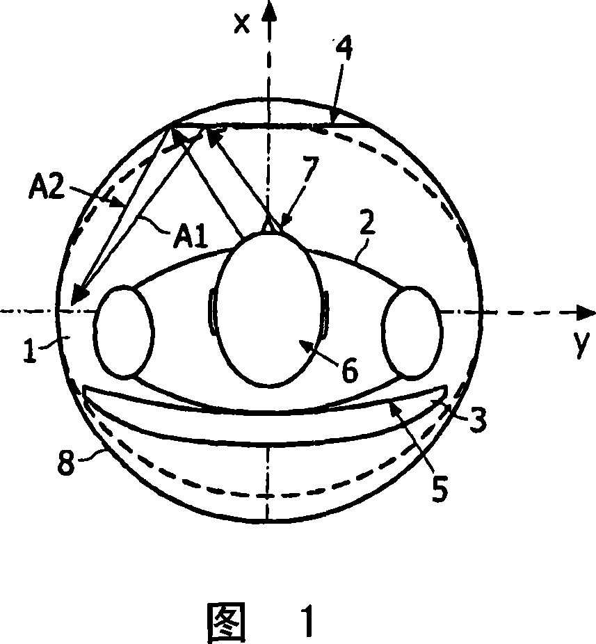
[0029] Fig. 1 shows a chamber 1 of a closed cylindrical MR device according to the invention. The graph is oriented along a longitudinal axis (z-axis, axis of symmetry) perpendicular to the x-axis and y-axis. The x-axis, y-axis, and z-axis represent a 3D coordinate system. The cavity has an inner diameter of 60 cm and has two openings in the xy plane.

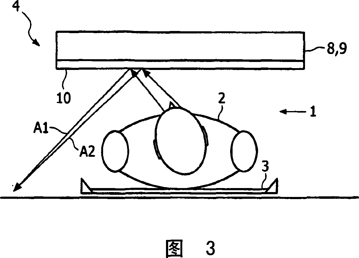
[0030] Inside the cavity is a patient 2 lying on a hospital bed 3 . Although the hospital bed 3 has a partially curved main surface 5, its central part is approximately flat, lying in the zy plane. The patient looks along the direction of the x-axis perpendicular to the main surface 5 of the hospital bed 3 . Above its head 6 is a plane mirror 4 arranged in the zy plane and thus parallel to the main surface 5 of the hospital bed 3 . The distance of the mirror from the center of the coordinate system is 27 cm. The distance between the center of the mirror 4 and the top cover 8 is 3cm.

[0031] The mirror is integrated into ...


PUM

PropertyMeasurementUnit
Diameteraaaaaaaaaa

Abstract

The invention relates to a medical examination apparatus, in particular an MR apparatus. Known MR apparatus have a cavity for accommodating the patient to be examined that offers only a limited space for the patient. The limited space may lead to claustrophobic reactions jeopardizing the result of a measurement. According to the invention a mirror (4), arranged in parallel to the main surface (5) of the patient's bed (3), is provided in the interior of the cavity (1). The mirror (4) simulates a larger space of the interior of the cavity and increases the patient's comfort.

Description

technical field [0001] The invention relates to a medical inspection device, which includes a cavity and a sick bed located in the cavity, wherein a target or a patient can receive electromagnetic waves in the cavity. The invention relates in particular to medical examination devices for MR (Magnetic Resonance) systems, MRI (Magnetic Resonance Imaging) systems, CT (Computed Tomography) systems or PET scanners. Background technique [0002] The MR system includes an at least partially enclosed cavity in which a patient or a part of the patient's body is located. In the examination space defined by the cavity, a static magnetic field is generated that fills the space. The signal of the RF (radio frequency) transmitter is coupled into the body, which causes a magnetic weakening of selected cell nuclei in the body. The nucleus absorbs RF energy and dissipates it during the relaxation time. The 3D (three-dimensional) study of the relaxation time distribution enables the acquis...

Claims


Application Information

Patent Timeline
IPC IPC(8): A61B5/055G01R33/28A61B6/03G02C7/14
CPCA61B6/037A61B6/032A61B5/055G01R33/283
Inventor C·L·G·哈姆F·A·德格拉夫
Owner KONINKLIJKE PHILIPS ELECTRONICS NV
Why Eureka
Try Eureka