Control system for multiphase rotary electric machine

A technology of rotating electric machines and multi-phase electric machines, which is applied in control systems, vector control systems, motor generator control, etc., and can solve problems such as internal combustion engine difficulties and no measures taken by hybrid locomotive systems

Active Publication Date: 2007-10-24
DENSO CORP
View PDF3 Cites 20 Cited by
  • Summary
  • Abstract
  • Description
  • Claims
  • Application Information

AI Technical Summary

Problems solved by technology

However, the occurrence of a short circuit may introduce load torque to the three-phase motor, making it difficult to properly transmit the output torque of the internal combustion engine to the drive wheels
[0009] The conventional control systems described above do not address the issues involved with hybrid locomotive systems

Method used


Image

  • Control system for multiphase rotary electric machine
  • Control system for multiphase rotary electric machine
  • Control system for multiphase rotary electric machine

Examples


no. 1 example

[0058] A first embodiment of the present invention is described below with reference to the drawings. In this embodiment, the multi-phase rotating electrical machine control system of the present invention is applied to a system loaded on a hybrid locomotive.

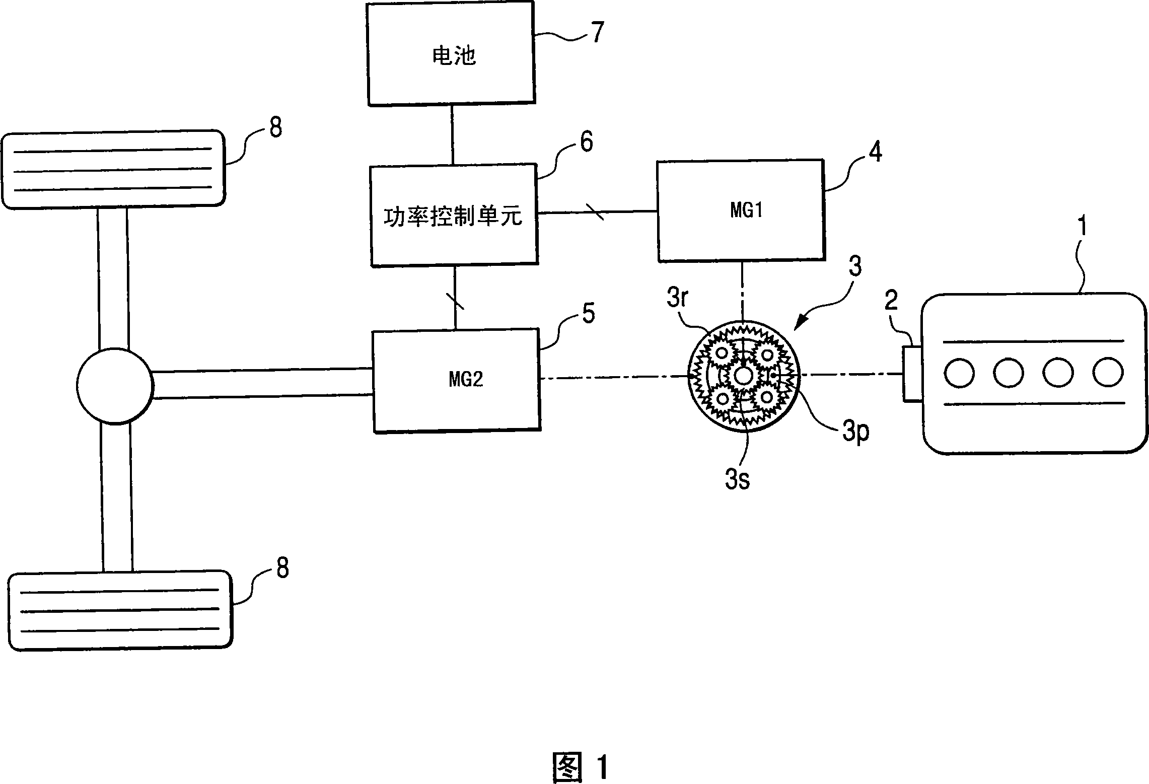
[0059] FIG. 1 is a schematic diagram showing a general configuration of a power transmission system of the hybrid locomotive described above.

[0060] As shown in FIG. 1 , an internal combustion engine 1 is provided with a flywheel damper 2 for suppressing vibration of the internal combustion engine 1 . The power of the internal combustion engine 1 is distributed to a first motor-generator (generator 4 ) and a second motor-generator (motor 5 ) through a torque split mechanism 3 . Specifically, the torque split mechanism 3 is composed of a planetary gear mechanism. In the planetary gear mechanism, the planetary gear 3p is connected to the rotating shaft of the internal combustion engine, the sun gear 3s is connected to...

no. 2 example

[0125] A second embodiment of the present invention is described below with reference to the drawings, focusing on differences from the first embodiment. In this embodiment and the following several embodiments, in order to simplify or omit some explanations, the same or similar components as those in the first embodiment are given the same symbols.

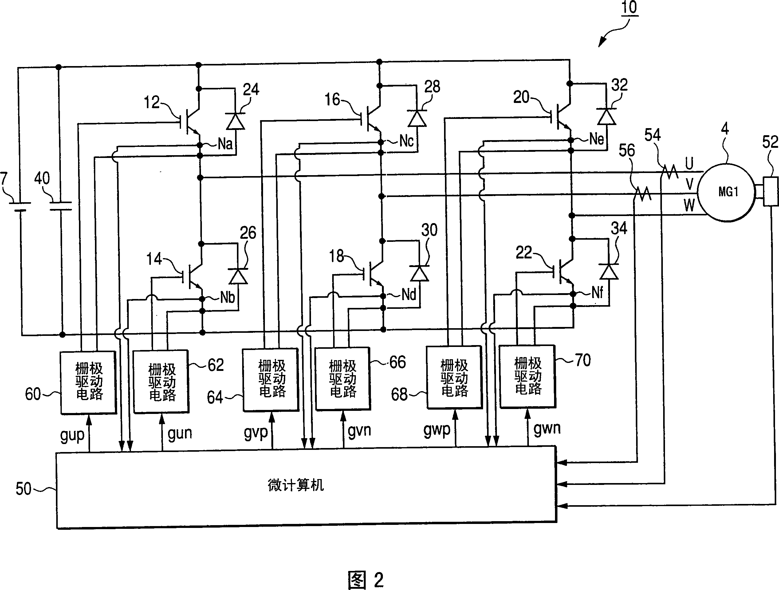
[0126] FIG. 14 shows the generator 4, the inverter 10, and the microcomputer 50 related to this embodiment.

[0127] As shown in FIG. 14 , the present embodiment is provided with switching circuits 130 , 132 and 134 connected between the outputs of the respective arms of the inverter 10 and the three phases of the generator 4 . These switches 130, 132 and 134 are normally closed switches, however may preferably be switches that do not close once in the open state. For example, these switching circuits 130, 132, and 134 may be relays provided to the output bus.

[0128] FIG. 15 shows the processing performed when a short circuit...

no. 3 example

[0133] A third embodiment according to the present invention is described below with reference to the drawings, focusing on differences from the second embodiment.

[0134] FIG. 16 shows the processing performed when a short circuit occurs according to the present embodiment. These processes are executed by the microcomputer 50 in predetermined cycles, for example.

[0135] In this series of processing, when any one of the switching elements 12, 14, 16, 18, 20, and 22 is determined to be short-circuited (step S40), it is determined at step S42 whether the switching circuits 130, 132, and 134 have been A disconnect operation was performed. In this regard, it is assumed that switching circuits 130, 132, and 134 remain unclosed once opened. Therefore, once the disconnection operation is performed, the series of processing shown in FIG. 16 ends.

[0136]On the other hand, if the disconnection operation is not performed, it is determined whether all the actual currents iu, ev an...


PUM


Abstract

A control system for multiphase rotary electric machines is provided. The control system carries out control of the output of a multiphase rotary electric machine by operating switching elements of an inverter, so that more appropriate measure can be taken when malfunction has occurred in the inverter. A rotary shaft of an internal combustion engine, a rotary shaft of a generator and a rotary shaft of a motor are linked through a torque-splitting mechanism. The control system carries out failsafe processes, at the occurrence of short circuit in a switching element of the inverter, to control load torque of the generator so as to prevent rotation of a rotary shaft of the internal combustion engine in a non-operative state, which rotation is induced by a motive force of the motor.

Description

[0001] References to related applications [0002] This application claims priority from prior Japanese Patent Applications 2006-116602 and 2006-286739 filed on April 20, 2006 and October 20, 2006, respectively, and the descriptions of these two applications are hereby incorporated by reference. technical field [0003] The present invention relates to a control system of a multi-phase rotating electrical machine, which controls the output of the multi-phase rotating electrical machine by operating switching elements in an inverter. Background technique [0004] In known control systems, the output torque of a three-phase motor is controlled by operating switching elements in an inverter. An inverter in such a control system has three arms for conducting each of the three phases of a three-phase motor with the positive or negative terminal of the supply voltage. In the control performed by such a system, a short circuit of the switching elements of any one arm of the invert...

Claims


Application Information

Patent Timeline
Patent Type & Authority Applications(China)
IPC IPC(8): H02M7/48H02P27/00B60L9/22H02P23/00B60K6/445B60L3/00B60L50/16B60W10/00B60W10/08B60W20/00B60W20/10B60W20/50H02P6/06H02P6/08H02P6/12H02P21/22H02P25/026H02P25/10H02P27/08
CPCY02T10/7077Y02T10/7241Y02T10/642Y02T10/6239Y02T10/6286Y02T10/7083Y02T10/62Y02T10/64Y02T10/7072
Inventor 辻浩也川崎新五宫地准二
Owner DENSO CORP
Why Eureka
Try Eureka