Check patentability & draft patents in minutes with Patsnap Eureka AI!

Optical modulator and optical modulation system

A light modulation device and light modulation technology, applied in optics, nonlinear optics, instruments, etc., can solve the problems of smaller aperture ratio and lower utilization efficiency, and achieve the effect of improving utilization efficiency

Inactive Publication Date: 2007-10-24
ROHM CO LTD
View PDF3 Cites 4 Cited by
  • Summary
  • Abstract
  • Description
  • Claims
  • Application Information

AI Technical Summary

Problems solved by technology

[0010] However, when the light is obliquely incident from the normal direction of the light incident surface, part of the incident light is blocked by the electrodes and cannot be emitted, so the aperture ratio becomes small, and there is a problem that the light utilization efficiency decreases.

Method used


Image

  • Optical modulator and optical modulation system
  • Optical modulator and optical modulation system
  • Optical modulator and optical modulation system

Examples


Embodiment Construction

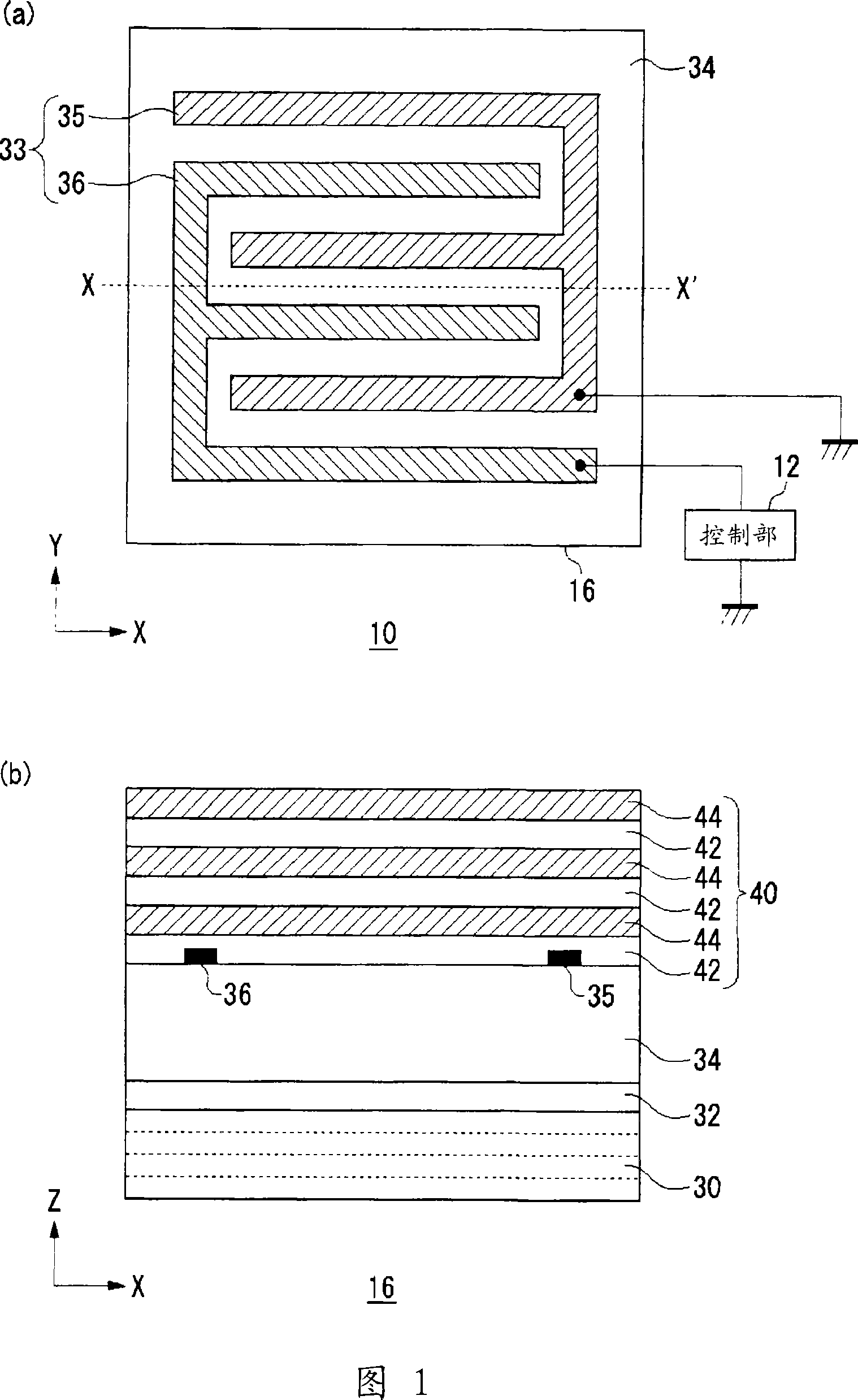
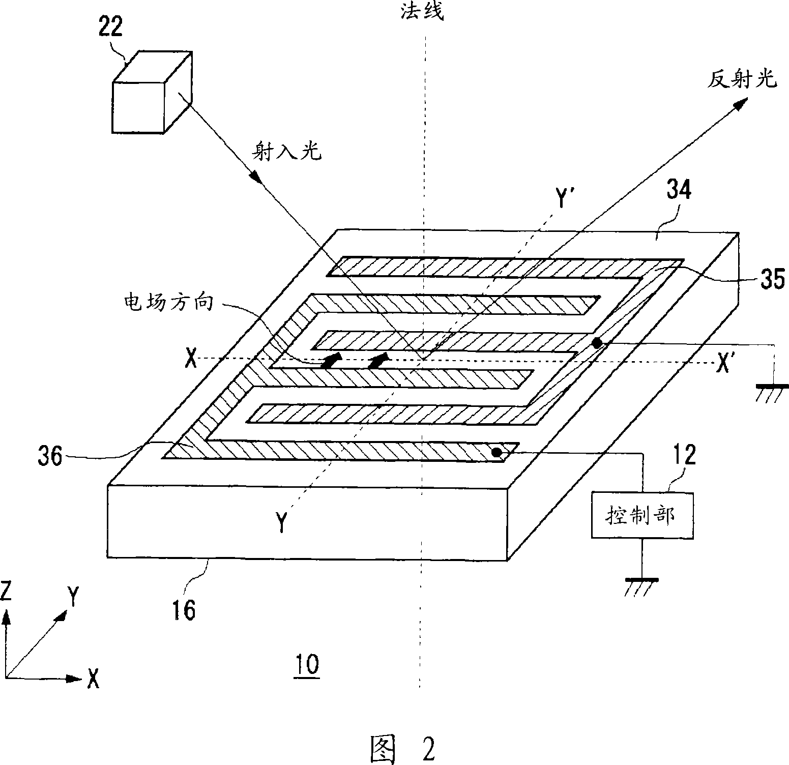
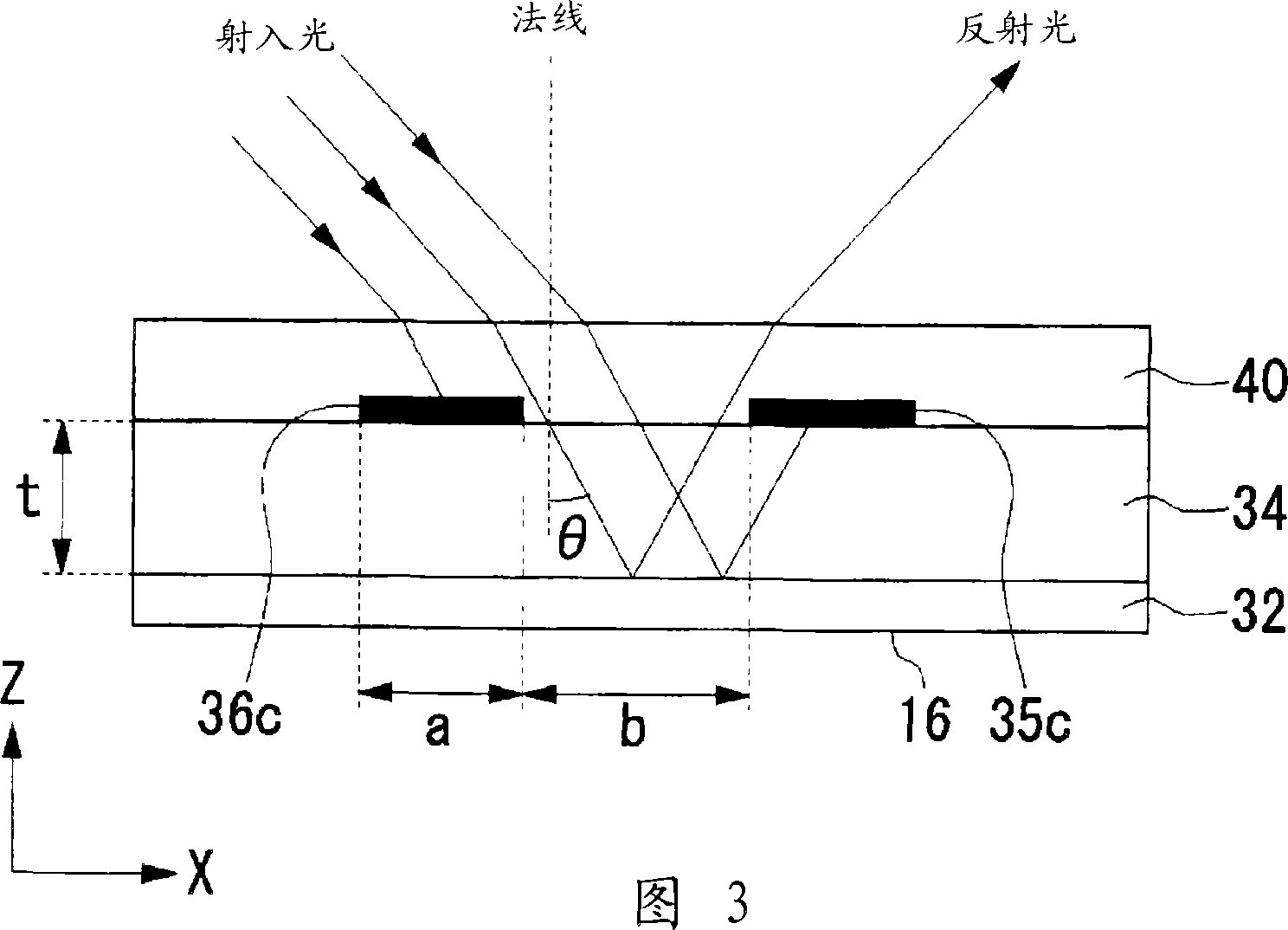
[0036] The light modulation device of this embodiment will be briefly described. This light modulation device is a light modulation device including a light modulation film whose refractive index changes according to an applied electric field. By applying a control voltage to the light modulation film and controlling the electric field applied to the light modulation film, the intensity of light emitted from the light modulation device can be changed. In this embodiment, the light emitted from the light emitting part is substantially perpendicular to the direction of the electric field applied to the light modulation film, and is inclined from the normal direction of the light incident surface to enter the light incident surface. For example, in the case where the two parallel electrodes are formed on the light modulation film to the light modulation device in the light modulation film, the absorption of light by the electrodes is reduced by injecting light from a direction su...


PUM

PropertyMeasurementUnit
thicknessaaaaaaaaaa
reflectanceaaaaaaaaaa

Abstract

Disclosed is an optical modulator improved in light use efficiency. Specifically disclosed is an optical modulator (10) comprising a light-emitting unit (22), a Fabry-Perot resonator (16), and a control unit (12) for applying a control voltage to the resonator (16). The resonator (16) comprises a light-modulating film (34) whose refractive index changes according to the electric field applied thereto, and comb electrodes (35, 36) for applying an electric field to the light-modulating film (34). The light emitted from the light-emitting unit (22) is incident on the light incident surface at an angle substantially perpendicular to the direction of the electric field applied to the light-modulating film (34) while being tilted from the normal direction of the light incident surface.

Description

technical field [0001] The present invention relates to a light modulation device and a light modulation system utilizing the electro-optic effect. Background technique [0002] In recent years, a digital information recording system utilizing the principle of holography has been known as a large-capacity recording method (for example, Patent Document 1). [0003] As a material for a spatial light modulator of a holographic recording device, for example, lead lanthanum zirconate titanate (hereinafter referred to as PLZT) having an electro-optic effect can be used. PLZT has (Pb 1-y La y )(Zr 1-X Ti X )O 3 composed of transparent ceramics. The electro-optic effect refers to a phenomenon in which when an electric field is applied to a substance, the substance is polarized and the refractive index changes. By using the electro-optical effect, the phase of light can be changed by turning on and off the applied voltage. Therefore, the light modulation material having the e...

Claims


Application Information

Patent Timeline
Patent Type & Authority Applications(China)
IPC IPC(8): G02F1/03
CPCG02F2201/305G02F2001/213G02F2201/124G02F1/0316G02F1/0311G02F1/21G02F1/213G02F1/03
Inventor 藤森敬和
Owner ROHM CO LTD
Features
  • R&D
  • Intellectual Property
  • Life Sciences
  • Materials
  • Tech Scout
  • Unparalleled Data Quality
  • Higher Quality Content
  • 60% Fewer Hallucinations
Learn More