

Magnetic shaker
A technology of magnetic force and magnetic system, applied in the field of shakers, can solve the problems of magnetic separation inclusions, etc., and achieve the effect of increasing the differential action, increasing the sorting efficiency, and improving the sorting effect.
- Summary
- Abstract
- Description
- Claims
- Application Information
AI Technical Summary
Problems solved by technology
Method used
Image

Examples
Embodiment 1
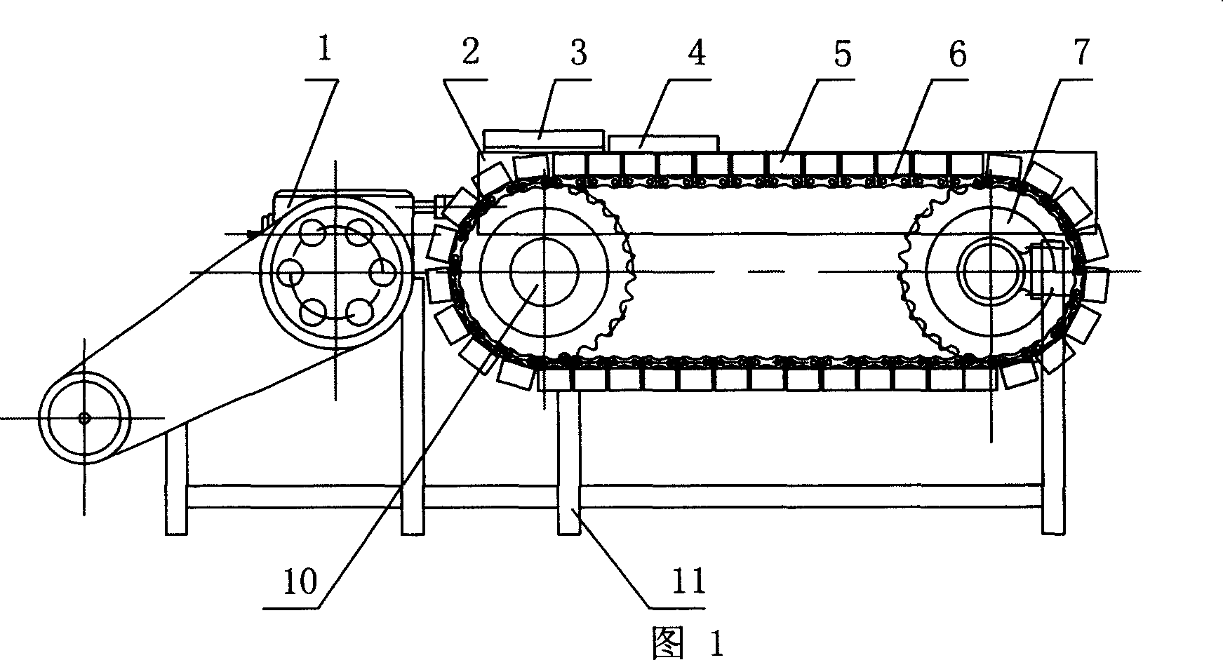
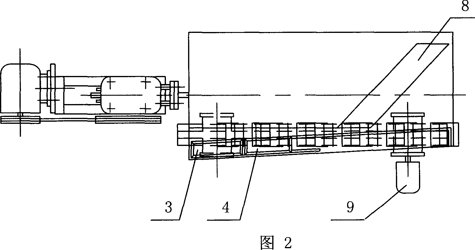
[0014] Embodiment 1, as shown in the figure, the present invention comprises support 11, is provided with head of a bed 1 and bed surface 2 on support 11, is respectively provided with ore feeding tank 3 and water supply tank 4 on bed surface 2, on bed surface Bed strips 8 are also provided. In addition, a drive mechanism 9 is also provided on the bracket, which may be a motor or the like. A magnetic system carrier mechanism 6 running along the direction of the bed surface is arranged under the bed surface 2 , and a magnetic system 5 is arranged on the magnetic system carrier mechanism 6 . The magnetic carrier mechanism 6 can be arranged vertically or horizontally.
[0015] The magnetic system carrier mechanism 6 in the present invention is composed of a driving sprocket 7 , a driven sprocket 10 and a transmission chain arranged between the driving sprocket 7 and the driven sprocket 10 . The magnetic carrier mechanism 6 is arranged along the length direction of the bed surfa...
Embodiment 2
[0017] Embodiment 2, as shown in the figure, the present invention comprises support 11, is provided with head of a bed 1 and bed surface 2 on support 11, is respectively provided with ore feeding tank 3 and water supply tank 4 on bed surface 2, on bed surface Bed strips 8 are also provided. In addition, a drive mechanism 9 is also provided on the bracket, which may be a motor or the like. A magnetic system carrier mechanism 6 running along the direction of the bed surface is arranged under the bed surface 2 , and a magnetic system 5 is arranged on the magnetic system carrier mechanism 6 . The magnetic carrier mechanism 6 can be arranged vertically or horizontally.
[0018] The magnetic system carrier mechanism 6 is composed of a driving wheel, a driven wheel and a conveyor belt arranged between the driving wheel and the driven wheel. The magnetic carrier mechanism 6 is arranged along the length direction of the bed surface. Alternatively, the magnetic carrier mechanism 6 i...
Embodiment 3
[0020] Embodiment 3, as shown in the figure, the present invention comprises support 11, is provided with head of a bed 1 and bed surface 2 on support 11, is respectively provided with ore feeding tank 3 and water supply tank 4 on bed surface 2, on bed surface Bed strips 8 are also provided. In addition, a drive mechanism 9 is also provided on the bracket, which may be a motor or the like. A magnetic system carrier mechanism 6 running along the direction of the bed surface is arranged under the bed surface 2 , and a magnetic system 5 is arranged on the magnetic system carrier mechanism 6 . The magnetic carrier mechanism 6 can be arranged vertically or horizontally.
[0021] The magnetic system carrier mechanism 6 includes a horizontal transmission track on which a moving magnetic system carrier is arranged. The magnetic carrier mechanism 6 is arranged along the length direction of the bed surface. Alternatively, the magnetic carrier mechanism 6 is arranged along the width d...
PUM
 Abstract
Description
Claims
Application Information