Coiling method for making nails
A wire-winding and wire-type technology, applied in the field of medical devices, can solve the problems that are difficult to meet the requirements of clinical use, the impact of surgical procedures, and difficult manufacturing and forming, and achieve the effects of high yield rate, good implementation effect, and low cost
- Summary
- Abstract
- Description
- Claims
- Application Information
AI Technical Summary
Problems solved by technology
Method used
Image

Examples
Embodiment 1
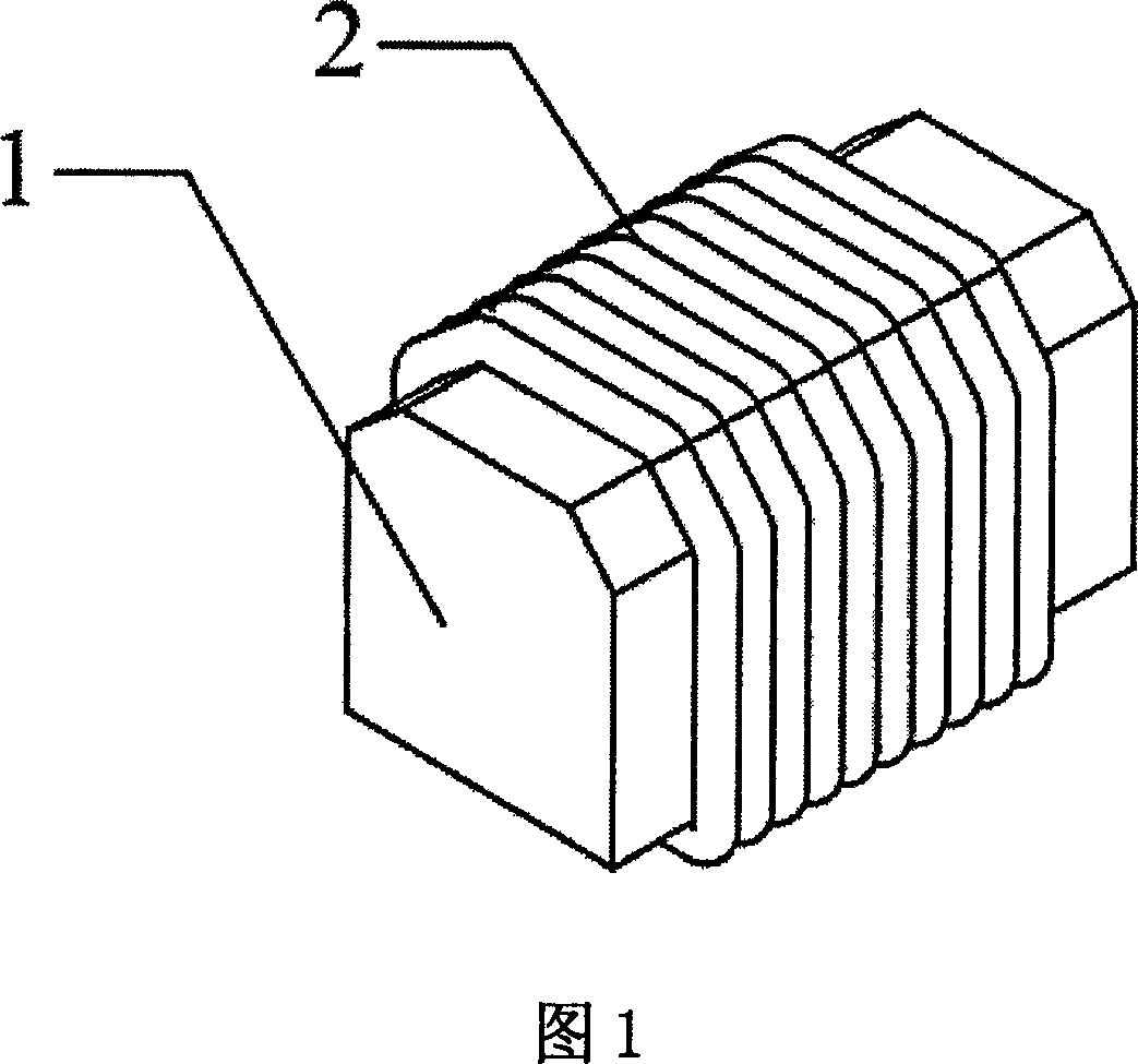
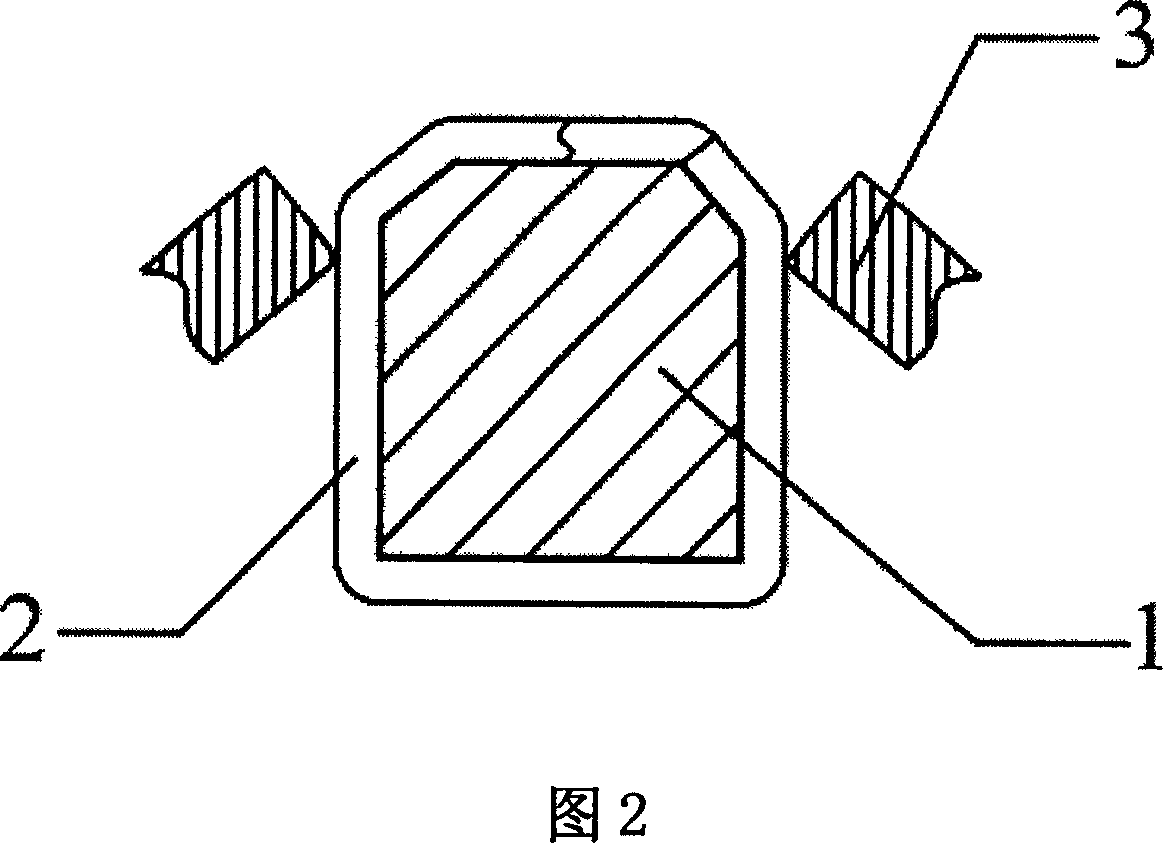
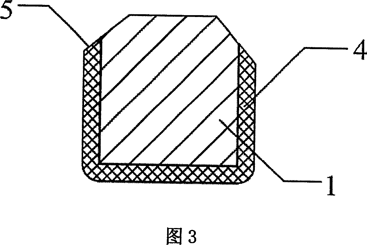
[0027] As shown in Figure 1: Use stainless steel wire or titanium wire with the same diameter as the nail used in the stapler as the linear nail-making raw material 2, and wind it tightly and evenly on the mold with symmetrical slopes 1. More specifically, the shape of the mold 1 is consistent with that of the nail 4, which is a cuboid with two chamfered slopes. During the winding process, two parts of the linear nail-making raw material 2 are attached to the symmetrical slope of the mold 1 . As shown in FIG. 2 : by using a grinding wheel or a file as a cutting tool 3 , the linear nail-making raw material 2 is cut along the symmetrical slope of the mold 1 to form a nail 4 . During the entire truncation process, the interception modes of the two interception tools 3 are interception simultaneously or step by step interception. When implementing step-by-step interception, the two ends of the linear nail-making raw material 2 can be properly fixed with clamps to ensure that the ...
Embodiment 2
[0029] As shown in FIG. 4 : the mold 11 is in the shape of an hourglass hourglass with two big ends and a narrow middle, and two symmetrical triangular cut positions 6 are arranged in the middle of the mold 11 .
[0030] As shown in Figure 5: when making nails, the linear nail-making raw material 2 is tightly wound on the mold 11, and the nail-making raw material 2 is selected, that is, a stainless steel wire or a titanium wire with the same diameter as the nail. It is tightly and evenly wound on the timing hourglass-shaped mold 11, and then, through two cutting tools 3, namely, grinding wheels or files, the nail-making raw material 2 is cut off along the triangular cut 6 on the mold. As shown in FIG. 6 : while forming the nail foot slope 5 , two rows of closely arranged nails 4 , that is, nail groups of two units, are made. At the same time, during the interception process, the interception mode of the two interception tools 3 may be simultaneous interception or step-by-step ...
Embodiment 3
[0032] As shown in Figure 7: a stainless steel wire or titanium wire with the same diameter as the nail is selected as the nail-making raw material 2, and is evenly wound on the mold 12 with a sharp angle, and the sharp angle is an isosceles triangle. As shown in Figure 8: the top of the nail making raw material 2 is cut off with the cutting tool 3, so that the two slopes 5 of the nail foot are formed. As shown in Figure 9: At this point, the stainless steel wire or titanium wire becomes a row of closely arranged wires with bends 7 . Finally, the mold 12 with a sharp angle is removed from the bend 7, and the bend 7 of the nail making raw material 2 straightens to become a row of closely arranged nails 4. In this process, clamps can be used on both sides of the nail-making raw material 2 near the bottom of the sharp-angle mold 12 to ensure that no single nail 4 falls off during the entire demoulding process, and the effect of removing the bend 7 is better.
PUM
 Abstract
Description
Claims
Application Information
 - R&D
- Intellectual Property
- Life Sciences
- Materials
- Tech Scout
- Unparalleled Data Quality
- Higher Quality Content
- 60% Fewer Hallucinations
Browse by: Latest US Patents, China's latest patents, Technical Efficacy Thesaurus, Application Domain, Technology Topic, Popular Technical Reports.
© 2025 PatSnap. All rights reserved.Legal|Privacy policy|Modern Slavery Act Transparency Statement|Sitemap|About US| Contact US: help@patsnap.com