Current for acceptor current enter and reflux

A current collector and current technology, applied in the direction of collectors, power collectors, electric vehicles, etc., can solve the problem of no return circuit facilities, and achieve the effect of avoiding the phenomenon of electric sparks and simplifying the mechanical structure.

Inactive Publication Date: 2007-10-31
SHANGHAI MAGNETIC SUSPENSION COMM ENG TECH RES CENTE +1
View PDF0 Cites 25 Cited by
  • Summary
  • Abstract
  • Description
  • Claims
  • Application Information

AI Technical Summary

Problems solved by technology

In addition, the existing current receiver is under the force of the elastic device, the power receiving shoe does not break away from the power supply rail, and there is only one power receiving shoe, and there is no return circuit facility

Method used


Image

  • Current for acceptor current enter and reflux
  • Current for acceptor current enter and reflux
  • Current for acceptor current enter and reflux

Examples


Embodiment Construction

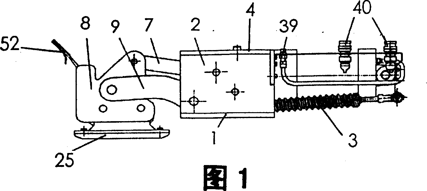
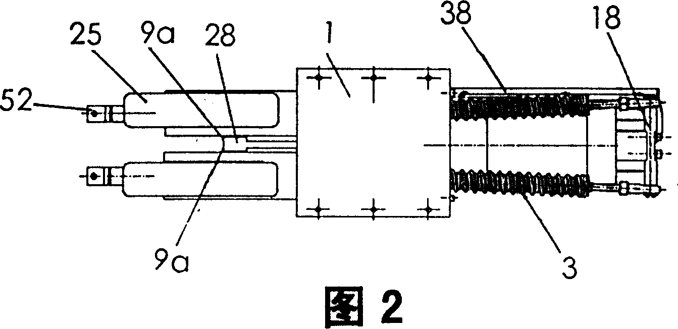
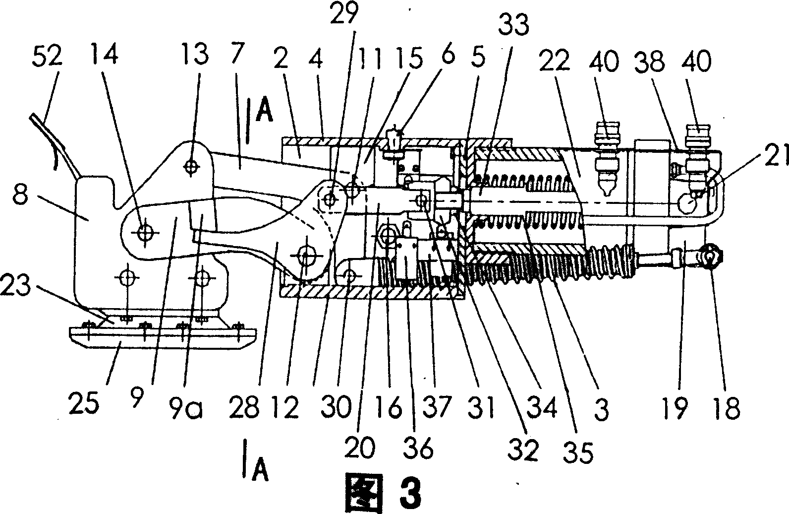
[0025] Please refer to Fig. 1 to shown in Fig. 3, each component of the present invention is installed on the square box body that is made up of base plate 1, left and right side plates 2, top cover plate 4, cylinder fixed end plate 5, and positioning pin is used between them Positioning, bolt tight connection. The bottom plate 1 is installed to realize the external connection, and the positioning pin 6 is installed on the top cover plate 4 for positioning when the collector is installed. The current receiver is provided with two sets of parallelogram four-bar linkages installed in parallel near the left and right side plates 2, each set of parallelogram four-bar linkages consists of an upper link 7, a lower link 9, and an insulating plate 8. , and a corresponding side plate 2, the installation hole distance of the upper link 7 is equal to the installation hole distance of the lower link 9, the installation hole distance of the insulating plate 8 is equal to the installation h...


PUM


Abstract

The invention relates to the electric receiving device of the electric vehicle. The current receiver for current in and return comprises the electric boots and the spring device, with two parallel parallelogram four linking bar structure and a separation structure, each four link structure made by the top and down lining bars hinged to the corresponding side plate and isolation plate, the separation structure composed of the air cylinder, air cylinder linking pole hinged to the cylinder piston end, lower linking brake bar with two rocker arms with the lower linking brake bar hinged to the lower linking bar pin shaft fixed to two side walls, one of the rocker arm hinged to the air cylinder linking bar, the other being the stop leaning against the low linking bar, each isolation plate bottom installed with an electric receiving boot, each four link bar structure having its top link bar connected to the said spring device. It solves the technical issues of current receiver contact or separation with the electric supply track smoothly, and the grounding issue of it.

Description

Technical field: [0001] The invention relates to a power receiving device of an electric vehicle, in particular to a power receiving and return device used in a high-speed magnetic levitation train. Background technique: [0002] Urban traffic such as light rail and subway are driven by electric power. There are catenary or power supply rails for power supply system along the line. Electricity, or through the contact of the current collector fixed at the bottom of the vehicle and the power supply rail to obtain electric energy. In addition, it is necessary to form a current loop through the walking contact of the wheels on the grounded track, so as to realize the driving of electric power and the power consumption of various equipment. Therefore, during the whole operation process, the pantograph or the current collector is always in contact with the catenary or the power supply rail. [0003] Maglev trains, especially high-speed maglev trains with a speed of more than 430...

Claims


Application Information

Patent Timeline
Patent Type & Authority Applications(China)
IPC IPC(8): B60L5/38
Inventor 王怀江何大海
Owner SHANGHAI MAGNETIC SUSPENSION COMM ENG TECH RES CENTE
Why Eureka
Try Eureka