Cushion cylinder device

A buffer cylinder and a new type of technology, applied in the field of cylinders and buffer cylinders, can solve the problems of freezing hydraulic oil, high noise of the air pressure buffer device, poor reliability, etc., and achieve the effect of low noise

Inactive Publication Date: 2007-10-31
JIANGSU TIANYU ENVIRONMENTAL PROTECTION GRP CO LTD
View PDF0 Cites 9 Cited by
  • Summary
  • Abstract
  • Description
  • Claims
  • Application Information

AI Technical Summary

Problems solved by technology

In the past, people installed elastic materials on the contact surface of two objects, such as rubber, sponge, etc., to protect the object and prevent the object from being damaged by impact. The advantage of this is low cost, and the disadvantage is short life and poor reliability.
On some large-mass, high-speed moving objects, such a buffering method is obviously not applicable; therefore, people use hydraulic and pneumatic buffering devices to achieve buffering, and a device with a buffering function is used to achieve buffering at a position close to the target. This device can When approaching the target position, decelerate until it stops smoothly, but the maintenance period of the hydraulic device is short, and the cost of use is relatively high. In cold regions, the hydraulic oil will freeze and the reliability is low; the air pressure buffer device is noisy and is often installed under the load. It itself has to bear the impact of the impact parts and is easily damaged

Method used


Image

  • Cushion cylinder device
  • Cushion cylinder device

Examples


Embodiment Construction

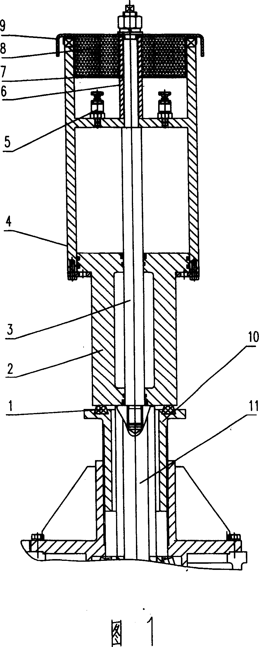
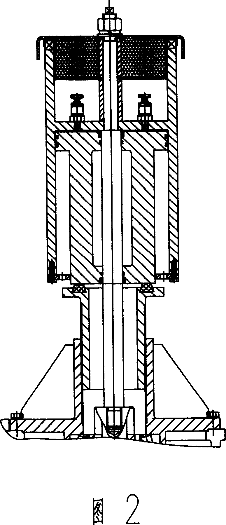
[0012] The bearing member 10 is provided with a middle hole, and the impact member 11 is arranged in the middle hole and can move freely. A buffer rubber ring 1 is arranged on the upper end surface of the bearing member 10. Corresponding to the upper end surface of the bearing member 10, a piston 2 and a piston rod 3 are arranged. It is installed in the middle hole of the piston 2, radially sealed, and can move freely; the upper part of the cylinder body 4 is provided with a silencer chamber, and the piston rod 3 passes through the cylinder body 4 and the silencer chamber, and the part of the piston rod 3 in the silencer chamber is empty. Set a spacer 6, the height of the spacer 6 is the same as that of the silencer chamber, the upper end of the spacer 6 and the silencer chamber is provided with a cover plate 9, the piston rod 3 continues to pass through the cover plate 9, and is fixedly connected with the cover plate 9, the silencer chamber There is a sound-absorbing material ...


PUM


Abstract

The invention relates to a novel cushion cylinder device, in particular to a technical field of cushion cylinder, which is vertically arranged and connects the bearing element and the striking element, comprising a cylinder, a piston and a piston rod, wherein a discharge valve is arranged on the top of the cylinder, the bottom end-face faces the bearing element, the piston is provided with a central hole, the piston rod traverses the central hole and can axially move in the piston, top of the piston rod passes the cylinder end-face and is connected with the cylinder, bottom of the piston rod is connected with the striking element. The invention makes the piston rod traverse the piston and be connected with the cylinder, to make the cylinder move respectively to the piston, when the piston touches the bearing element, the striking element drives the cylinder to move downward and the compressed air in the cylinder can be discharged via a noise-reduction baffler to slow down the velocity of the relative movement to realize the cushion, the design combined with the noise-reduction cavity can make the noise during the cushion of cylinder lower. The invention is applicable to cushion generated during the heavy-load impact element strikes the bearing element at high speed, in particular to the cold area.

Description

technical field [0001] The invention relates to a cylinder, in particular to the technical field of a buffer cylinder. Background technique [0002] Objects moving at high speed will collide with the joint surface when they reach the target stroke. In the past, people installed elastic materials on the contact surface of two objects, such as rubber, sponge, etc., to protect the object and prevent the object from being damaged by impact. The advantage of this is low cost, but the disadvantage is short life and poor reliability. On some large-mass, high-speed moving objects, such a buffering method is obviously not applicable; therefore, people use hydraulic and pneumatic buffering devices to achieve buffering, and a device with a buffering function is used to achieve buffering at a position close to the target. This device can When approaching the target position, decelerate until it stops smoothly, but the maintenance period of the hydraulic device is short, and the cost of...

Claims


Application Information

Patent Timeline
Patent Type & Authority Applications(China)
IPC IPC(8): F16F9/02
Inventor 王明根徐乃东
Owner JIANGSU TIANYU ENVIRONMENTAL PROTECTION GRP CO LTD
Why Eureka
Try Eureka