Heat exchanger

A heat exchanger and heat sink technology, applied in heat exchange equipment, heating methods, household heating, etc., can solve the problems of wind flow obstruction, inability to strengthen the heat sink, unable to increase the rigidity of the heat sink, etc., and achieve increased strength , smooth flow effect

Inactive Publication Date: 2007-10-31
DAIKIN IND LTD
View PDF1 Cites 3 Cited by
  • Summary
  • Abstract
  • Description
  • Claims
  • Application Information

AI Technical Summary

Problems solved by technology

[0006] However, in the above-mentioned conventional heat exchanger, since the above-mentioned protrusions extend in a direction different from the longitudinal direction of the fins, it is not possible to sufficiently reinforce in the longitudinal direction which has the greatest influence on the strength of the fins. The problem of efficient heat sink reinforcement
[0007] In addition, in the above-mentioned conventional heat exchanger, when the diameter of the insertion hole is large, or when the minimum value between adjacent insertion holes is small, or when the width of the fin is narrow, there is a problem that even if the ridge is formed, it cannot The problem of increasing the rigidity of the heat sink
[0008] In addition, in the above-mentioned conventional heat exchanger, if the height of the protrusions provided on the fins is high, the flow of the wind flowing outside the tubes will be hindered, and the heat exchange efficiency of the heat exchanger will decrease.

Method used


Image

  • Heat exchanger
  • Heat exchanger
  • Heat exchanger

Examples


no. 1 approach

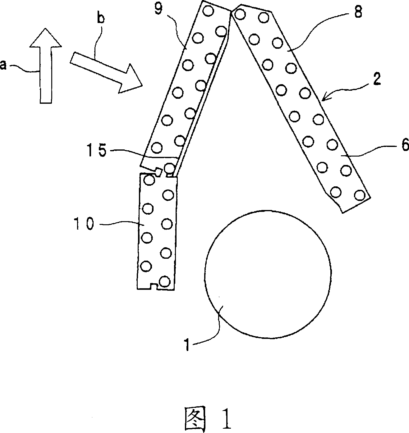
[0051] Fig. 1 is a schematic sectional view of an air conditioner using a heat exchanger according to a first embodiment of the present invention. In Fig. 1, 1 is a blower fan, and 2 is a heat exchanger. In addition, in FIG. 1 , arrow a indicates the vertically upward direction when the heat exchanger is arranged in the air conditioner in use, and arrow b indicates the flow direction of wind as the heat transfer medium. In FIG. 1 , for the sake of brevity, the case for accommodating the blower fan 1 and the heat exchanger 2 and the like are omitted.

[0052] In this air conditioner, the blower fan 1 is rotated, and the air sucked in via the heat exchanger 2 is blown out from an air outlet not shown.

[0053]The heat exchanger 2 has a fan 6 and heat transfer tubes (not shown). The plurality of fans 6 are arranged at predetermined intervals in a direction perpendicular to the paper surface in FIG. 1 . The above-mentioned fan 6 is in the shape of a flat plate. The above-menti...

no. 2 approach

[0088] Fig. 4 is a partial enlarged view of the second portion 79 of the fin 73 included in the heat exchanger of the second embodiment. The heat exchanger of the second embodiment differs from the heat exchanger of the first embodiment only in that, in the second part 79, the row of the insertion holes 72 for the insertion of the heat transfer tubes arranged in a staggered direction in the width direction is different from that of the first embodiment. A second rib 76 is formed therebetween, and the second rib 76 is substantially parallel to the first rib 75 and has substantially the same shape as the first rib 75 .


PUM


Abstract

The invention provides a heat exchanger. On a fin (6), a rib (15) extending substantially parallel to an external edge (25) of the fin (6) is formed, and through holes (22) for penetrating a heat exchanger tube are arranged zigzag. When the inner diameter of the through holes (22) is D[mm], a distance between the center of the through hole (22) and the external edge (25) is L[mm], a distance between the center of the rib (15) and the external edge (25) is La[mm], the width of the rib (15) is LL1[mm], the plate thickness of the fin (6) is t[mm], the height of the rib (15) is h1[mm], and the minimum value of a distance between the through holes (22) is P[mm], the through holes (22) and the rib (15) satisfying the following inequalities are formed; 0.4 F28F 1 / 32 F25B 39 / 00 5 11 2 2005 / 11 / 22 101065636 2007 / 10 / 31 000000000 Daikin Ind Ltd. Japan Kitazawa Masaaki Taira Shigeharu dangxiao lin 11127 San You Patent Agency No.201 Entrance 1, Building 13, the East of Jinmenli, Haidian District, Beijing 100088 Japan 2004 / 11 / 25 340321 / 2004 2007 / 5 / 24 PCT / JP2005 / 021422 2005 / 11 / 22 WO2006 / 057235 2006 / 6 / 1 Japanese

Description

technical field [0001] The invention relates to a heat exchanger, in particular to a heat exchanger suitable for use in an air conditioner. Background technique [0002] Conventionally, as a heat exchanger, there exists a heat exchanger described in Unexamined-Japanese-Patent No. 2-309195 (patent document 1). [0003] The heat exchanger has fins and tubes. The heat sink is formed of a rectangular flat plate. A plurality of the cooling fins are arranged at intervals. A plurality of insertion holes through which the tubes are inserted are formed on the above-mentioned cooling fins. The above-mentioned multiple through-holes are arranged in a staggered manner on the heat sink. In addition, a plurality of substantially linear protrusions are formed between the staggered insertion holes in the heat sink. The plurality of protrusions are formed in a state substantially parallel to each other. The protrusions extend in a direction different from the longitudinal direction of ...

Claims


Application Information

Patent Timeline
Patent Type & Authority Applications(China)
IPC IPC(8): F28F1/32F25B39/00F24F1/0067
CPCF24F1/0059F28F1/32F24F1/0067
Inventor 北泽昌昭平良繁治
Owner DAIKIN IND LTD
Why Eureka
Try Eureka