Circular granular sludge reactor

A granular sludge and reactor technology, which is applied in the field of circulating granular sludge reactors, can solve the problems of affecting the processing capacity of anaerobic reactors, insufficient bacterial activity, and dead zones in reactors. Small, high load, and the effect of preventing the loss of bacteria

Inactive Publication Date: 2007-11-07
山东美泉环保科技有限公司
View PDF0 Cites 23 Cited by
  • Summary
  • Abstract
  • Description
  • Claims
  • Application Information

AI Technical Summary

Problems solved by technology

At the same time, due to the serious loss of strains in the original anaerobic process, common water distribution methods have problems such as uneven water distrib

Method used


Image

  • Circular granular sludge reactor
  • Circular granular sludge reactor

Examples


Example Embodiment

[0025] The present invention will be further described below in conjunction with the accompanying drawings and embodiments.

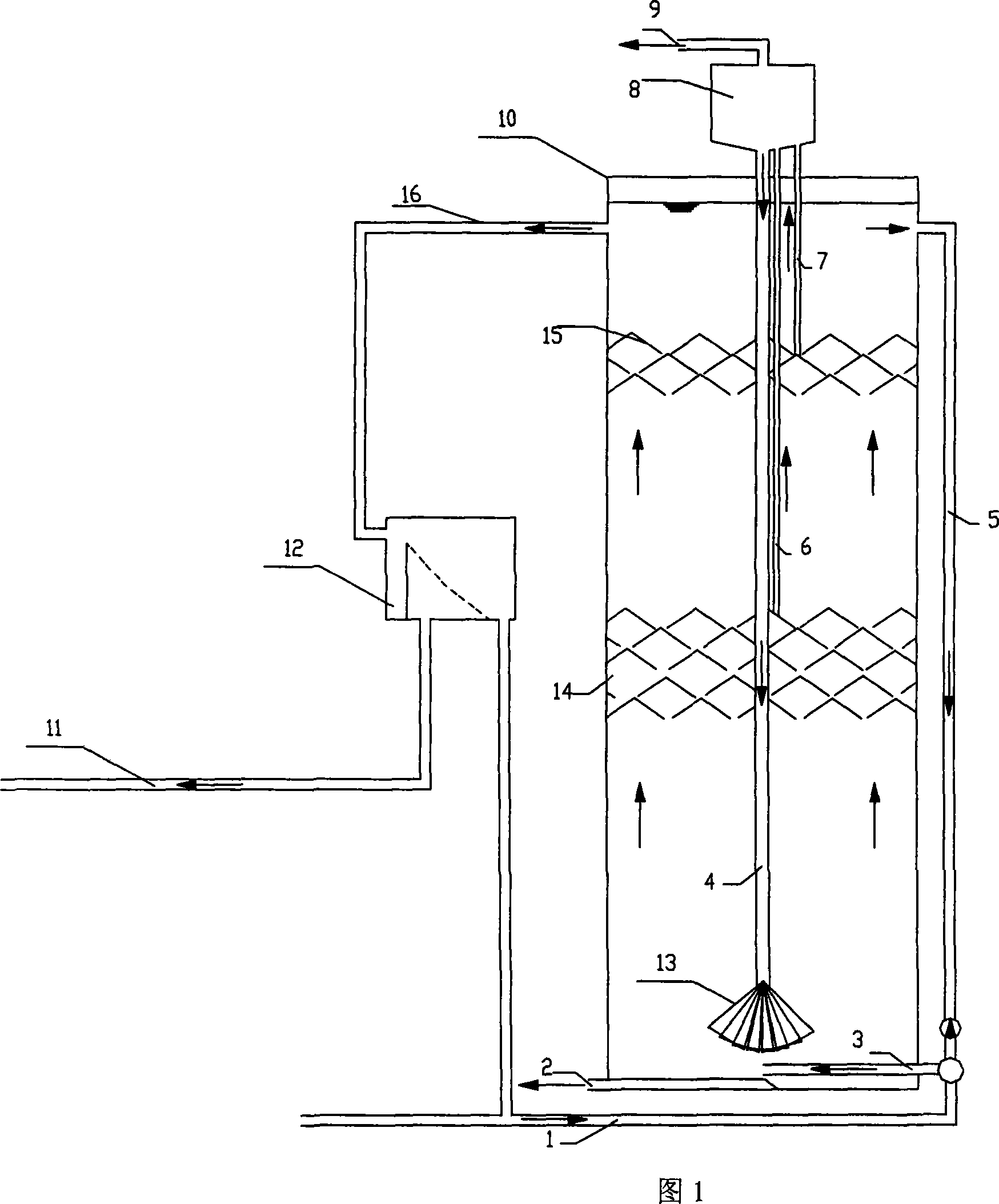
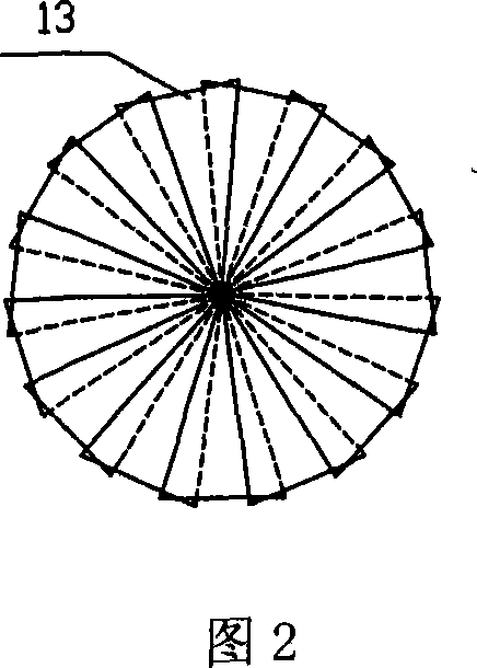
[0026] In FIG. 1 , a water distribution pipe 3 and a mud discharge pipe 2 are provided in the lower part of the multi-load anaerobic reactor tank body 10 , and the water distribution pipe 3 communicates with the water inlet pipe 1 . The first layer of three-phase separator 14 and the second layer of three-phase separator 15 inside the multi-load anaerobic reactor tank body 10 are provided with a steam-water separator 8 at the top, which communicates with the internal circulation pipe 4, and the end of the internal circulation pipe 4 A spiral water distributor 13 is provided. The steam-water separator 8 communicates with one end of the biogas riser I6 and biogas riser II7 respectively, the other end of the biogas riser I6 is located at the first layer of three-phase separator 14, and the other end of the biogas riser II7 is located at the second layer of...


PUM


Abstract

The present invention discloses one kind of circular granular sludge reactor with great load capacity, stable running, simple structure and other advantages. The circular granular sludge reactor has the structure including several anaerobic reactor tanks, each of which has a water distributor connected to the water inlet pipe and a sludge exhausting unit in the lower part, at least one layer of triphase separator with top vapor-water separator connected to the inner circulating pipe and methane lifting unit, an outer return pipe connected to the water inlet pipe, an outer circulating unit and a granular sludge circulating unit.

Description

technical field [0001] The invention relates to an anaerobic reactor for water treatment, in particular to a circulating granular sludge reactor relying on the joint action of internal circulation and external circulation. Background technique [0002] With the rapid development of industry and the continuous increase of population, the problems of energy, resources and environment have become increasingly serious. In the past 30 years, the shortage of energy has become more prominent. Using traditional aerobic biological treatment methods to treat wastewater consumes a lot of energy. The energy consumption for wastewater treatment in developed countries has accounted for about 1% of the country's total electricity consumption. The essence of aerobic biological treatment of wastewater is a technical measure to improve the quality of wastewater to meet the requirements of water environment quality by using the consumption of electric energy. Therefore, aerobic biological tre...

Claims


Application Information

Patent Timeline
IPC IPC(8): C02F3/28
CPCY02E50/343Y02E50/30
Inventor 乔壮明杨永和张科王平任雪亭朱杰高
Owner 山东美泉环保科技有限公司
Why Eureka
Try Eureka