Process of preparing fiber preformrod
An optical fiber preform and preform technology, applied in glass manufacturing equipment, manufacturing tools, glass production, etc., can solve problems such as poor resistance to hydrogen damage, reduce hydroxyl content, eliminate network structure defects, and excellent resistance to environmental hydrogen influence Effect
Active Publication Date: 2007-11-07
JIANGSU FASTEN CO LTD
View PDF2 Cites 9 Cited by
- Summary
- Abstract
- Description
- Claims
- Application Information
AI Technical Summary
Problems solved by technology
This separate process is more advantageous than the process of one-time deposition and sintering into rods in the tube in terms of eliminating internal moisture; however, the resulting quartz rods contain hydroxyl groups, which have poor resistance to hydrogen damage, and the attenuation coefficient of 1383nm after hydrogen aging The increase is greater than 0.005dB / km
Method used
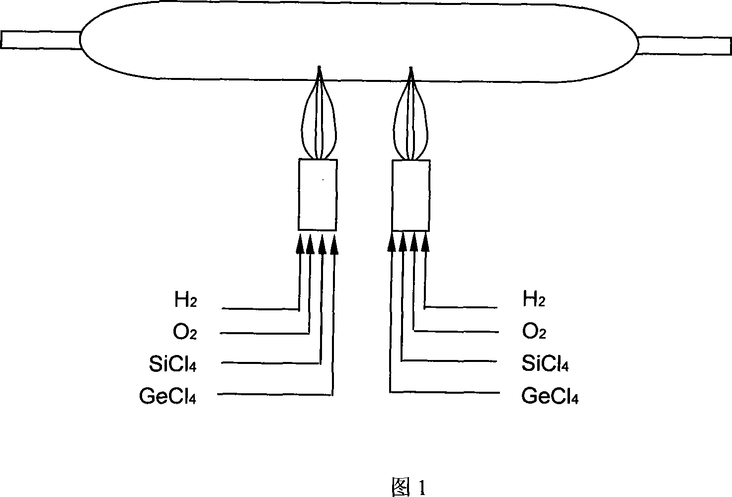
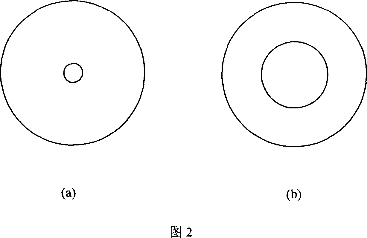
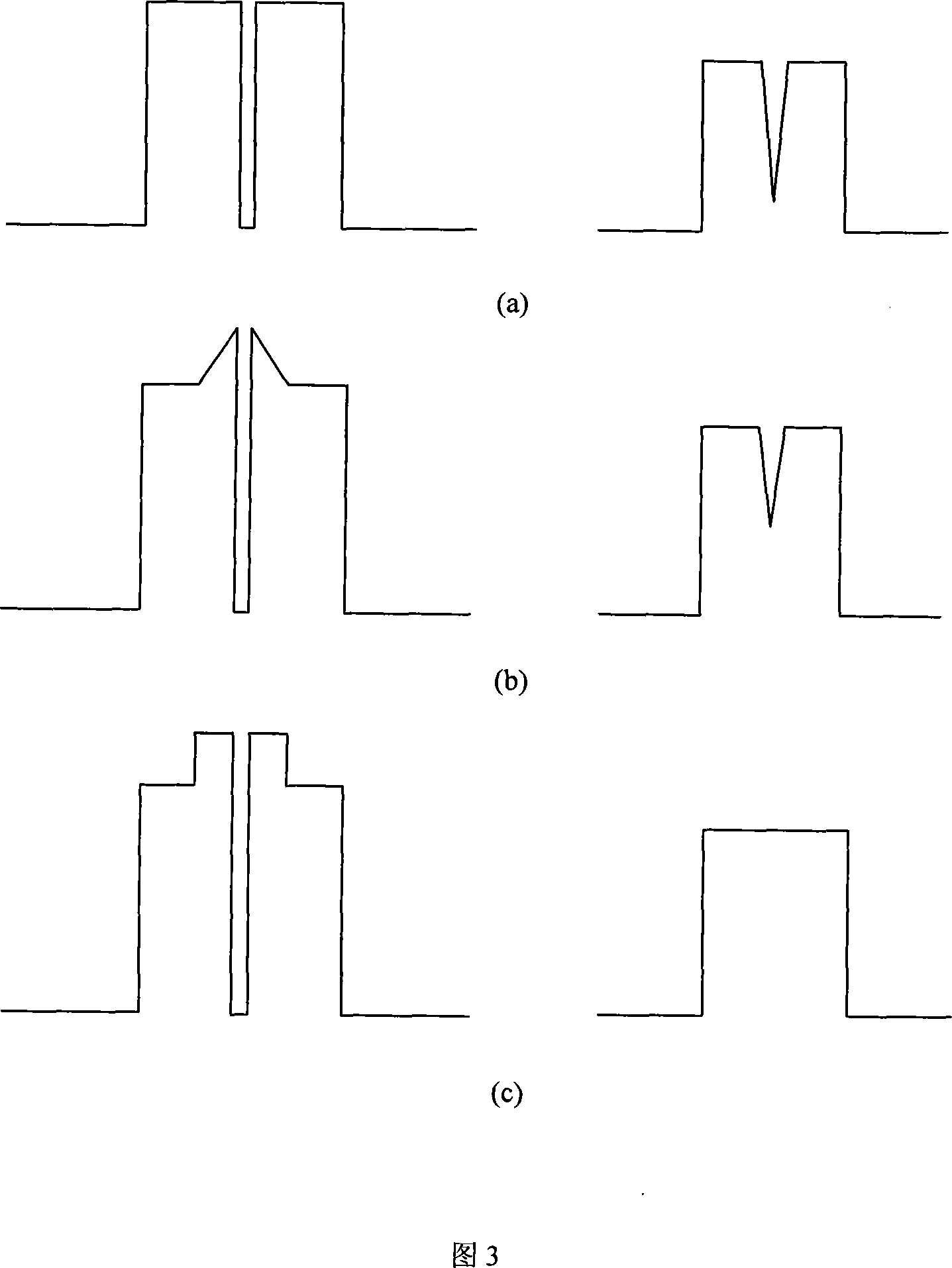
View moreImage
Smart ImageViewing Examples
Examples
Embodiment 1
[0043] 1310nm
Embodiment 2
[0045] 1310nm
Embodiment 3
[0047] 1310nm
Login to View More PUM
 Abstract
The process of preparing fiber preformed rod includes deuterium-hydrogen displacement reaction on quartz rod with low hydroxyl radical content and high purity for deuterium atom to occupy the non-bridge oxygen bond in quartz glass so as to reduce the probability of hydroxyl radical to diffuse, plasma flame etching to eliminate surface adsorbed hydroxyl radical of the quartz rod completely, depositing GeO2 and SiO2 onto the surface of the quartz rod, combined loose perform rod with central quartz rod, and dewatering and sintering in a sintering furnace to obtain transparent fiber preformed rod. The present invention is suitable for large- scale production and has low production cost, and the fiber preformed rod may be drawn into mono-mode fiber with low attenuation at 1383 nm wavelength, high hydrogen ageing resistance and very low PMD.
Description
1. Technical field [0001] The invention relates to a preparation method of an optical fiber preform, in particular to a preparation method of an optical fiber preform for producing a low water peak optical fiber by reducing the hydroxyl content in the optical fiber preform by an external deposition (OVD) process. 2. Background technology [0002] The transmission loss of conventional single-mode fiber (G.652B) is relatively high in the wavelength range of 1360-1460nm, which affects the application of optical communication systems in this band. Increased internal loss. Since the main vibrational absorption peak of OH is around 1383nm, the absorption peak at 1383±3nm is customarily called the water peak. ITU-T stipulates that the G652C specification requires that after the optical fiber undergoes hydrogen damage, its maximum attenuation coefficient of 1383±3nm must be less than or equal to the attenuation coefficient specified at 1310nm, and this kind of optical fiber is gene...
Claims
Login to View More Application Information
Patent Timeline
 IPC IPC(8): C03B37/018
CPCC03B37/0148C03B37/01466C03B2201/22C03B37/01413C03B37/01446C03B2201/31Y02P40/57
Inventor 查健江冯术娟严薇曲风西李兴元江锋尤茂勇陆剑锋吴江卞进良梁乐天
Owner JIANGSU FASTEN CO LTD
Features
- R&D
- Intellectual Property
- Life Sciences
- Materials
- Tech Scout
- Unparalleled Data Quality
- Higher Quality Content
- 60% Fewer Hallucinations
Learn More Browse by: Latest US Patents, China's latest patents, Technical Efficacy Thesaurus, Application Domain, Technology Topic, Popular Technical Reports.
© 2025 PatSnap. All rights reserved.Legal|Privacy policy|Modern Slavery Act Transparency Statement|Sitemap|About US| Contact US: help@patsnap.com


