Supercharge Your Innovation With Domain-Expert AI Agents!

Pneumatic clamping device

A pneumatic clamping and collet technology, applied in the direction of the chuck, can solve the problems of high production cost, complex assembly process, huge pneumatic rotating cylinder, etc., and achieve the effect of low production cost and simple assembly process

Inactive Publication Date: 2007-11-14
SHANDONG LUNAN MACHINE TOOL
View PDF0 Cites 5 Cited by
  • Summary
  • Abstract
  • Description
  • Claims
  • Application Information

AI Technical Summary

Problems solved by technology

[0002] At present, the machine tool clamping devices used in machining workpieces mainly include: rotating spindle and rotating cylinder; there is a pneumatic chuck at the front end of the rotating spindle, and the rotating cylinder is installed at the tail of the rotating spindle of the machine tool. There are pull rods and cylinders on the rotating cylinder. The pneumatic chuck at the front end of the main rotating shaft is connected, and the piston on the rotating cylinder moves to move the pull rod on the rotating cylinder, thereby driving the pneumatic chuck to expand and contract; the workpiece on the chuck is clamped or loosened. Although the clamping device can also realize the automation of workpiece clamping, it needs a huge pneumatic rotary cylinder, which makes the production cost high, the organization production cycle is long, and the assembly process is complicated

Method used


Image

  • Pneumatic clamping device
  • Pneumatic clamping device
  • Pneumatic clamping device

Examples


Embodiment Construction

[0011] The present invention will be further described below in conjunction with accompanying drawing and specific embodiment;

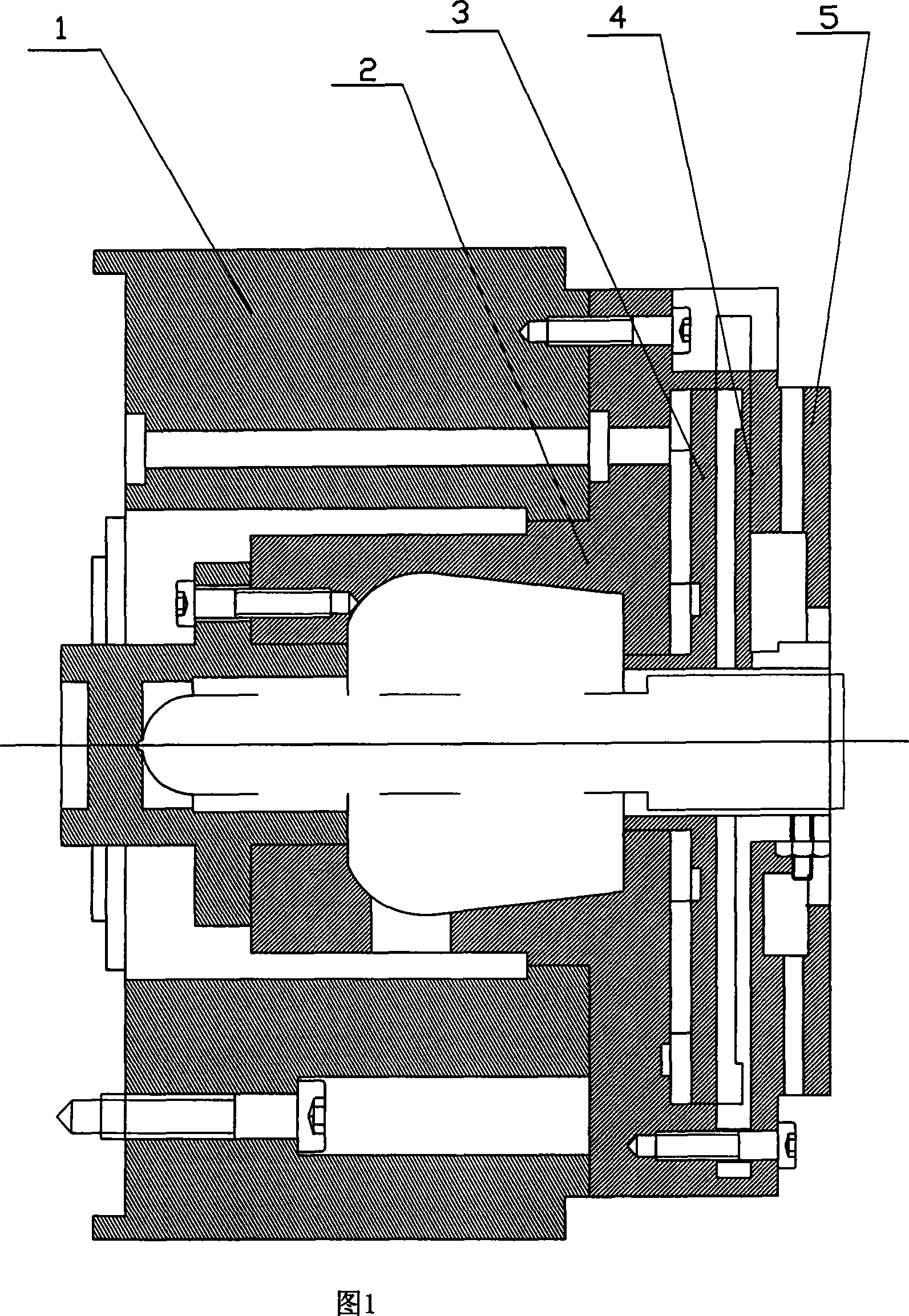
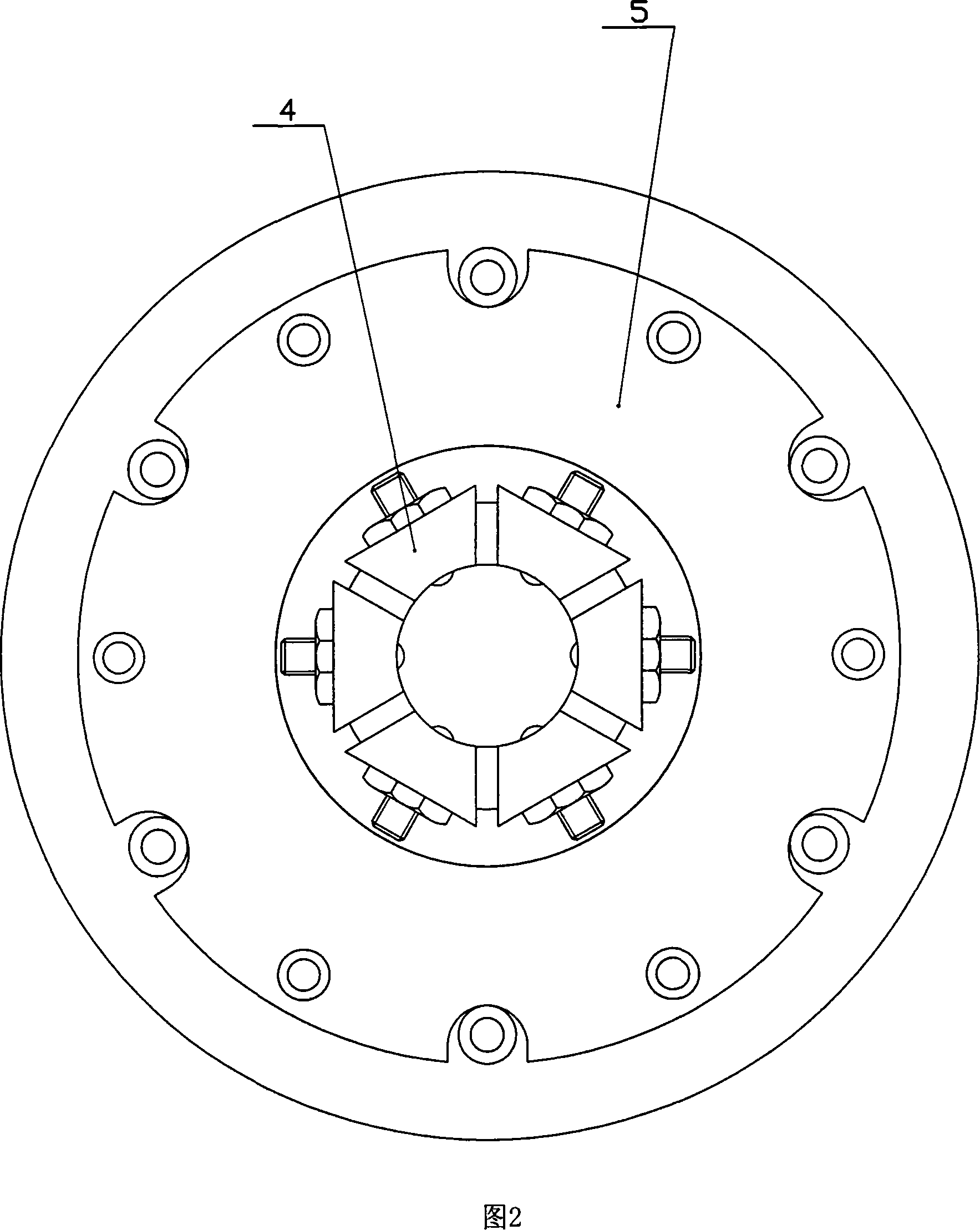
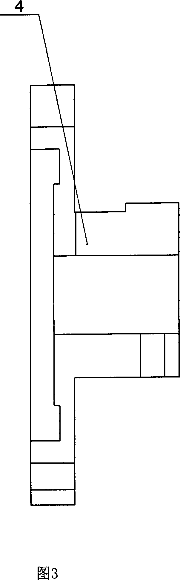
[0012] A pneumatic clamping device, as shown in Figures 1, 2, 3, 4, and 5, which includes: common machine tool spindles and collets; the collet is a collet 4, and the front end of the machine tool spindle is designed with a fixed seat 1 to fix Seat 1 is fixed on the spindle of the machine tool through screws, and the front end of the fixed seat 1 is designed with a collet body 2. The collet body 2 is mounted on the fixed seat 1 through screws, and the spring collet 4 is fixed on the collet body 2 through screws; The front end of the head body 2 is designed with a pressure 5, and the gland 5 is fixed and installed on the chuck body 2 by screws; the chuck body 2, the spring clip 4, and the gland 5 together form a sealed cylinder, and a piston is installed in the cylinder 3.

[0013] The working principle of the present invention is: the gas enters the...


PUM


Abstract

A low-cost and simple assembly process pneumatic clamp device contains a machine tool spindle and a collet . A fixed seat is fixed by bolts on the spindle of the machine tool. The chuck body is fitted on the fixed seat. The collet chuck fixed is fixed on the chuck body. A gland is fixed on the front end of the chuck body. The chuck body, collet chuck and the gland together form a sealed cylinder with a piston in it. The invention has advantages of simple technology and low cost.

Description

technical field [0001] The present invention relates to a machining tool, in particular to a pneumatic clamping device used in machining metal cutting. Background technique [0002] At present, the machine tool clamping devices used in machining workpieces mainly include: rotating spindle and rotating cylinder; there is a pneumatic chuck at the front end of the rotating spindle, and the rotating cylinder is installed at the tail of the rotating spindle of the machine tool. There are pull rods and cylinders on the rotating cylinder. The pneumatic chuck at the front end of the main rotating shaft is connected, and the piston on the rotating cylinder moves to move the pull rod on the rotating cylinder, thereby driving the pneumatic chuck to expand and contract; the workpiece on the chuck is clamped or loosened. Although the clamping device can also realize the automation of workpiece clamping, it needs a huge pneumatic rotary cylinder, which makes the production cost high, the ...

Claims


Application Information

Patent Timeline
IPC IPC(8): B23B31/30
Inventor 侯夫启王桂东王文孝梁家裕崔怀德国兴洋王其松
Owner SHANDONG LUNAN MACHINE TOOL
Features
  • R&D
  • Intellectual Property
  • Life Sciences
  • Materials
  • Tech Scout
  • Unparalleled Data Quality
  • Higher Quality Content
  • 60% Fewer Hallucinations
Learn More