Single-driving foot sandwiched transducer type longitudinal bending linear ultrasonic motor

A linear ultrasonic motor, transducer technology, applied in the direction of generator/motor, piezoelectric effect/electrostrictive or magnetostrictive motor, electrical components, etc., to achieve improved performance, good speed stability, improved amplitude and The effect of vibration

Inactive Publication Date: 2010-07-14
HARBIN INST OF TECH
View PDF2 Cites 0 Cited by
  • Summary
  • Abstract
  • Description
  • Claims
  • Application Information

AI Technical Summary

Problems solved by technology

[0003] In order to solve the problems of low moving speed, small thrust and low motor efficiency of the existing linear ultrasonic motor, the present invention further provides a single-drive foot-sandwich transducer type Longitudinal bending linear ultrasonic motor

Method used


Image

  • Single-driving foot sandwiched transducer type longitudinal bending linear ultrasonic motor
  • Single-driving foot sandwiched transducer type longitudinal bending linear ultrasonic motor
  • Single-driving foot sandwiched transducer type longitudinal bending linear ultrasonic motor

Examples


specific Embodiment approach 1

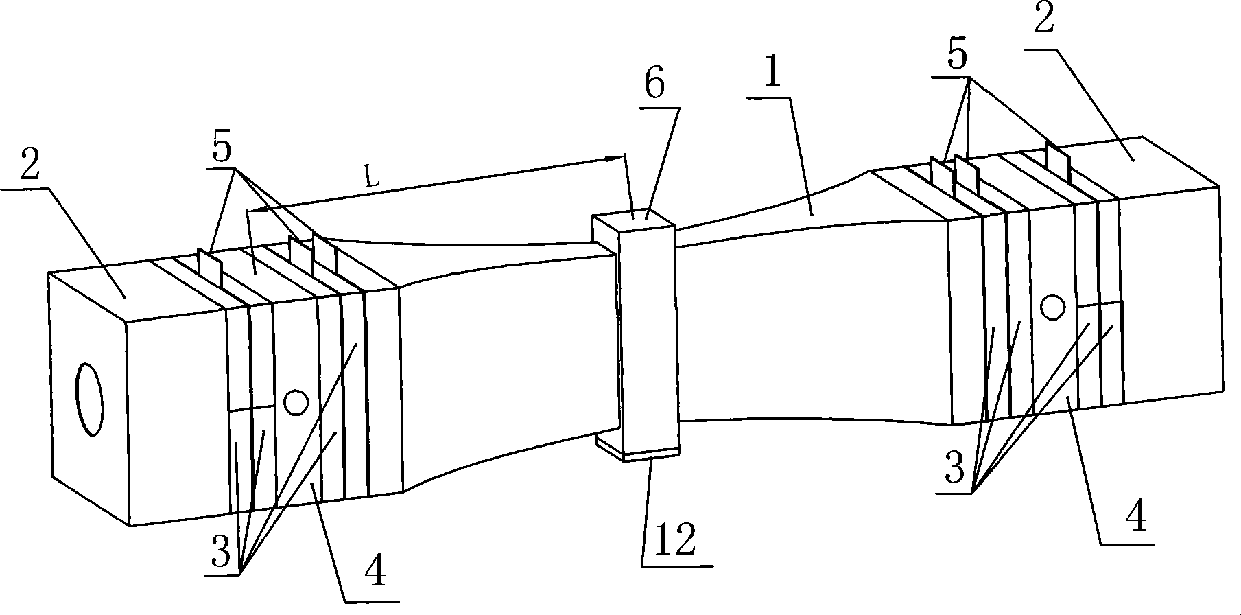
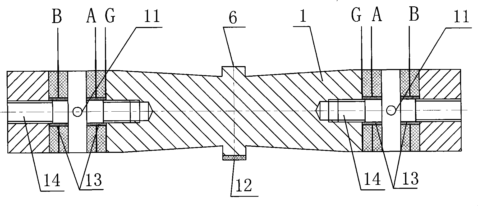
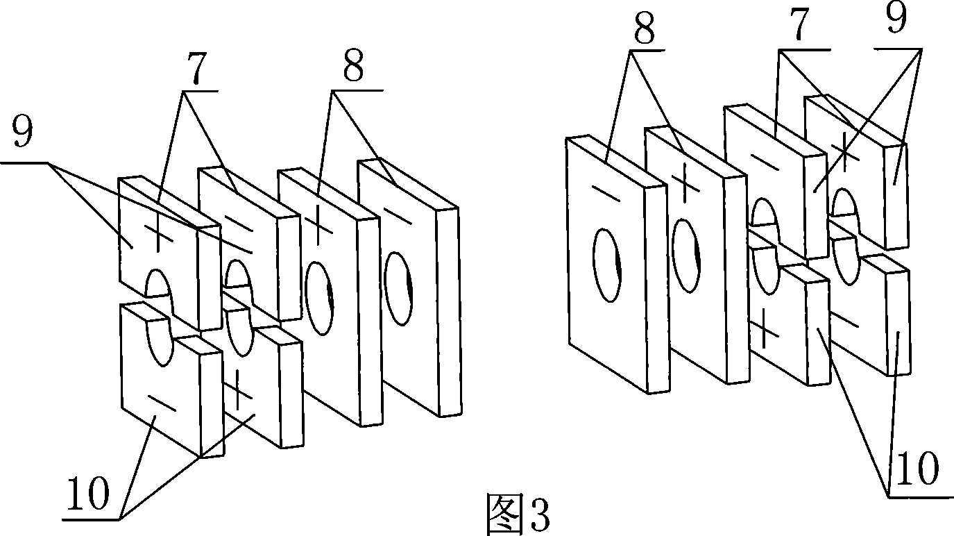
[0009] Specific implementation mode one: combine figure 1 , figure 2 and image 3 To illustrate this embodiment, the single-drive foot sandwich transducer type vertical bending linear ultrasonic motor of this embodiment is composed of a sandwich transducer and a drive foot 6, and the sandwich transducer is composed of a horn 1, two ends Cover 2, two groups of piezoelectric ceramic sheets 3, two flange studs, and thin copper sheet 5; the flange studs are composed of flanges 4 and studs 14, and the middle position on the studs 14 is fixed. There is a flange 4; the horn 1 is a quadrangular body whose cross-section gradually becomes thinner from both ends to the middle, and the driving foot 6 is located in the middle of the horn 1, and the piezoelectric ceramic sheet group 3 It is composed of two bending vibration piezoelectric ceramic sheets 7 and two longitudinal vibration piezoelectric ceramic sheets 8, and two bending vibration piezoelectric ceramic sheets 7 are installed ...

specific Embodiment approach 2

[0010] Specific implementation mode two: as figure 1 , figure 2 As shown, the horn 1 and the driving foot 6 are processed from a single piece of metal material. Reduce energy loss, simple structure and easy processing.

specific Embodiment approach 3

[0011] Specific implementation mode three: as figure 1 As shown, the upper end cross-section and the lower end cross-section of the driving foot 6 are both rectangular. Adopting such a structure can make the driving foot 6 fully contact with the plane of the guide rail, and improve the motion stability of the linear ultrasonic motor. Other components and connections are the same as those in the first embodiment.


PUM


Abstract

The disclosed variation pole is quadrangular body with rectangular section thinned gradually from two ends to central section. Drive feet are located at middle position of the pole. Piezoelectric ceramic piece in longitudinal vibration and piezoelectric ceramic piece in bending vibration are respectively installed on inner and outer sides of bolts on two flange bolts. Two end plates are installedon outer sides of bolts on two flange bolts. Through two flange bolts, two end plates, two groups of piezoelectric ceramic piece, and thin copper sheet are fastened and integrated to two larger ends of the pole. Advantages are: simple structure, smooth operation, large output thrust, and motion in high speed.

Description

technical field [0001] The invention relates to a linear ultrasonic motor and belongs to the technical field of piezoelectric ultrasonic motors. Background technique [0002] Ultrasonic motor is a motor that uses ultrasonic vibration energy and generates driving force through friction. It has the advantages of low speed and high torque (thrust), no need for transmission mechanism, no electromagnetic interference, fast response and self-locking when power is off. It has a very wide range of applications as a piezoelectric driver. At present, the motion speed of all linear ultrasonic motors generally does not exceed 1m / s when the driving voltage is lower than 100V, and the output thrust is generally less than 30N, which seriously restricts the application of linear ultrasonic motors in high-speed and high-power occasions. Contents of the invention [0003] In order to solve the problems of low moving speed, small thrust and low motor efficiency of the existing linear ult...

Claims


Application Information

Patent Timeline
Patent Type & Authority Patents(China)
IPC IPC(8): H02N2/08
Inventor 陈维山石胜君姚郁刘军考谢涛
Owner HARBIN INST OF TECH
Why Eureka
Try Eureka