Self-defined Ethernet optronic interface performance test method and device

A photoelectric interface and Ethernet technology, applied in electrical components, data exchange networks, electromagnetic wave transmission systems, etc., can solve the problems of complex test methods, increased production costs, and diverse test equipment, so as to save test connection time and save time and cost , The effect of saving production and testing costs

Inactive Publication Date: 2007-11-14
WUHAN FIBERHOME NETWORKS
View PDF0 Cites 20 Cited by
  • Summary
  • Abstract
  • Description
  • Claims
  • Application Information

AI Technical Summary

Problems solved by technology

[0008] If these tests are divided into single items and step-by-step tests, it will take a lot of time, and the test methods are complicated and the test equipment is diverse, so the production cost will increase accordingly

Method used


Image

  • Self-defined Ethernet optronic interface performance test method and device
  • Self-defined Ethernet optronic interface performance test method and device
  • Self-defined Ethernet optronic interface performance test method and device

Examples


Embodiment Construction

[0025] The specific implementation manners of the present invention will be described in detail below in conjunction with the accompanying drawings.

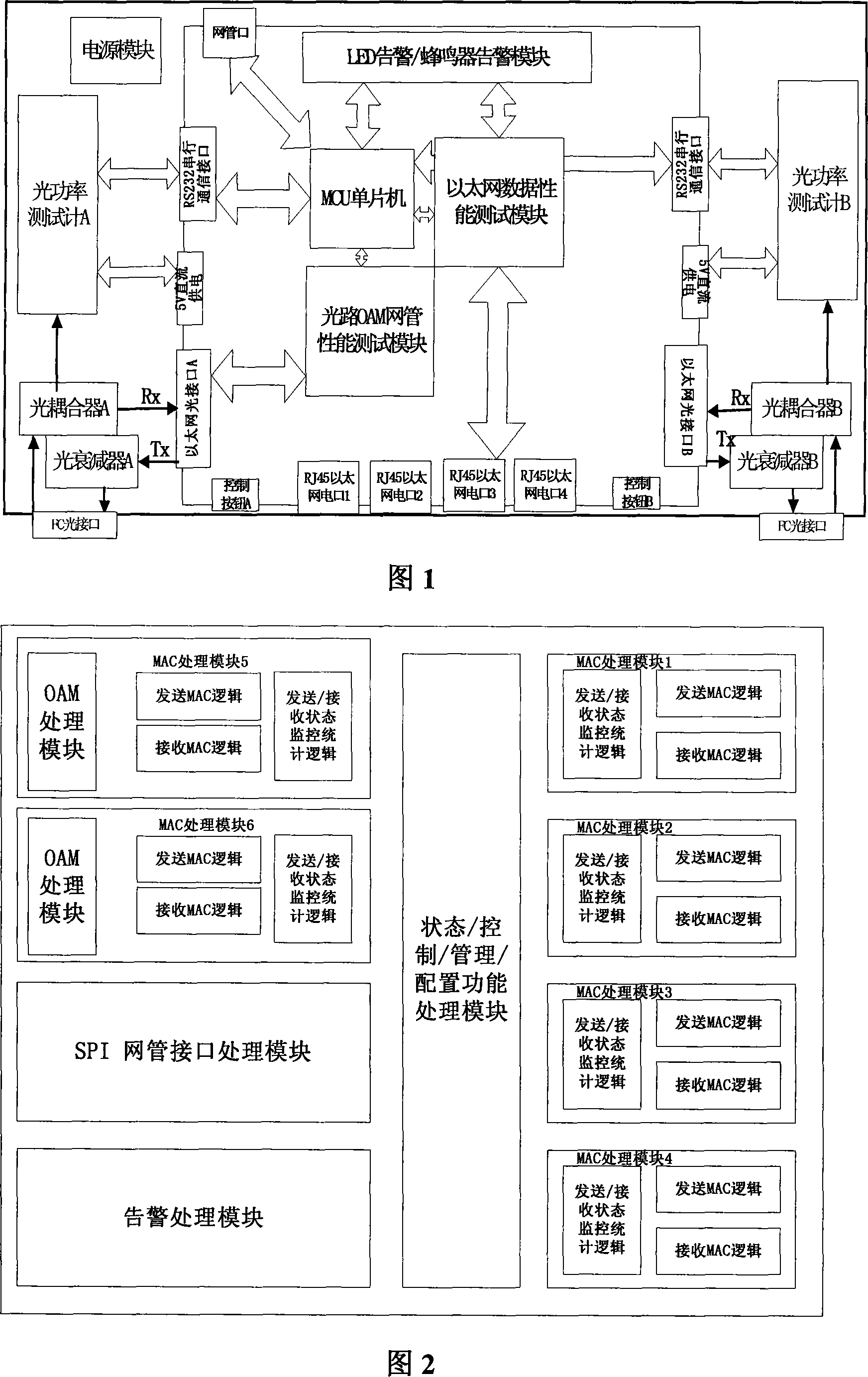
[0026] The overall block diagram of the device of the present invention is shown in Figure 1, and its structure includes an optical power test module, an adjustable optical attenuator module (model CAT-HV-135-09-0.6-FC / PC-SC / PC), an optical coupler module (model WBC-12-135-05-09-0.6-MU / PC-FC / PC-B), and the Ethernet data test logic module, the adjustable optical attenuator is set in the sending direction of the Ethernet optical port, and the optical The coupler is set in the receiving direction of the Ethernet optical port, and the two split lights of the optical coupler are respectively sent to the optical power test module and the Ethernet data test logic module. The Ethernet data test logic module includes a data channel module and a test control module. It monitors the remote network management of the device under test, and a...


PUM


Abstract

Specially, the invention is related to method and device for testing performance of new type self-defined photoelectric interface of Ethernet (PIE). An adjustable optical attenuator (AOA) is setup at sending direction of optical port of Ethernet. Data packet sent by the Ethernet data test logic module (EDTLM) passes AOA, which adjusts degree of decay of the sent light, and measures light receiving sensitivity of optical fiber transceiver. A light coupler is setup at receiving direction of optical port of Ethernet. The input light passing through the light coupler is split into two routes: one route is sent to light power test module; and the other route is sent to EDTLM at same time. The invention tests performance of optical interface, and tests luminescence power of device to be tested. The invention realizes testing performance of PIE through 'one key pushed'. Features are: easy of operation, quick test, and low testing cost.

Description

technical field [0001] The invention belongs to the technical field of 10 / 100M Ethernet testing, in particular to a method and device for testing the performance of a novel self-defined Ethernet optical interface. Background technique [0002] At present, with the rapid development of Ethernet, the demand for Ethernet equipment is getting stronger and stronger, and the production cycle of products is correspondingly shortened and shortened. Therefore, under the premise of little change in production capacity, the contradiction between the increase in product quantity and the shortening of product production cycle is unprecedentedly before us, which puts forward the requirement for us to streamline every link of the production process. Among them, product testing is a crucial link for a product. It is indispensable in the production process and plays an important role in strict control, but at the same time it occupies and consumes a lot of resources and time costs. [0003]...

Claims


Application Information

Patent Timeline
IPC IPC(8): H04B10/08H04B10/12H04L12/26H04B10/079
Inventor 夏惠龙
Owner WUHAN FIBERHOME NETWORKS
Why Eureka
Try Eureka