Cutter and cutting method

A technology of slitting machine and slitting knife, which is applied in metal processing and other directions, can solve the problems of poor reliability, high manufacturing cost, and inability to solve the problem of plastic adhesion, etc., and achieve the effect of novel structural design and free slitting

Inactive Publication Date: 2007-11-21
杭州中凌广告器材有限公司
View PDF1 Cites 10 Cited by
  • Summary
  • Abstract
  • Description
  • Claims
  • Application Information

AI Technical Summary

Problems solved by technology

Its shortcomings: first, the structure is complicated, the manufacturing cost is high, and the reliability is poor; the second is that it cannot solve the problem of plastic softening caused by friction and self-heating and the bonding between layers, and even the problem of spontaneous combustion caused by heat

Method used


Image

  • Cutter and cutting method

Examples


Embodiment 1

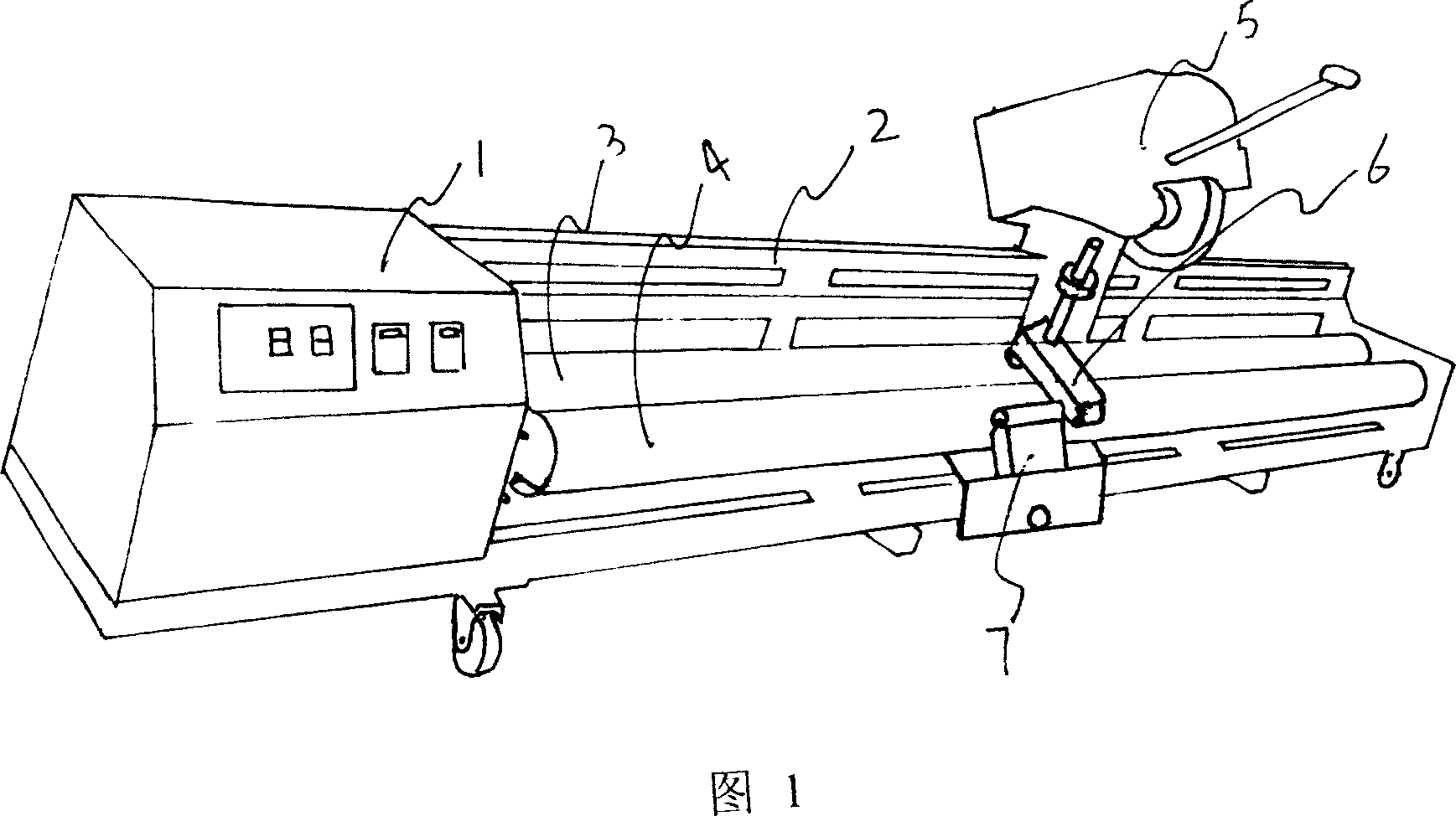
[0009] Embodiment 1: with reference to accompanying drawing 1. The slitting machine, the driving roller 3 and the driven roller 4 are manufactured using the prior art and the two ends of the driving roller 3 and the driven roller 4 are respectively located in the shaft seats at the two ends of the frame 2, and the driving roller 3 or the driven roller 4 pass through The transmission 1 is driven by a motor, and the driving roller 3 and the driven roller 4 are in clearance fit. Slitting knife assembly 5 is positioned at the roller surface that driving roll and driven roll form and can move back and forth along the crossbeam of frame, and slitting knife assembly 5 can move downward around the axis under the effect of external force. The waste cloth guide mechanism 7 is located on the frame before the driven roller 4 and can move back and forth along the frame beam. The roller surface of the cloth guide roller in the waste material guide mechanism 7 is in contact with the roller s...

Embodiment 2

[0010] Embodiment 2: On the basis of Embodiment 1, the slitting method of the slitting machine, the slit roll cloth or roll tape or roll film is placed between the roll surface formed by the driving roll and the driven roll, and the slitting knife is always The pressing mechanism in the process moves down and presses the cut cloth or tape or film. The motor drives the driving roller to rotate through the transmission and drives the cloth or tape or film to rotate. The cutter head in the cutter mechanism In the process of the cutter mechanism moving down step by step under the action of external force, the slit roll cloth or tape or roll film is cut, and the slit waste cloth located between the two cutter heads enters the guide roller and the waste cloth guide mechanism. Between the driven rollers and under the action of the driven roller and the guide roller, the waste cloth is led out until the cut cloth or tape or film is cut.


PUM


Abstract

The invention is concerned with the cutting for lamp housing sari, knife sari, gridding sari, transparence film, and transparence film rolling, it is: the initiative roller and the driven roller locates in the axle base of both ends of the stander, the motor drives initiative roller by transmission, the cutting knife assembly locates on the roller surface forming by the initiative roller and the driven roller, and traverses along the beam of the stander, fluctuates along the axle. The advantages are: two knives assume spacing arrangement, solves the problem that friction heat when cut the soft rolling material leads to the plastic softening and adhesion; it is easy and quick to cut the softness material; the structure is new, special and simple.

Description

Technical field: [0001] The invention relates to a slitter used for light box rolling cloth, knife scraping rolling cloth, grid rolling cloth, transparent film and transparent film roll, and belongs to the field of advertising equipment manufacturing. Background technique: [0002] The patent number is 01230391.7, and the name is "Multifunctional Tape Slitting Machine". Features are: A. single-knife cutting system: by handwheel (1), leading screw (2), screw nut (17), single-cut knife rest support (18), sliding shaft (19), rolling bearing (20) use multiple Screw combination is on the nut (17), single cutter rest (16), pin shaft (15), single cutter handle bar (11), loading force plate (25), single cutter (23), positioning pin (24 ), pin sleeve (29), one end of the single-cut hand lever (11) is welded on the pin shaft (15), and the pin shaft (15) is movable and worn in the pin sleeve (29), and the pin sleeve is welded on the single cutter On the frame support (18), the single...

Claims


Application Information

Patent Timeline
Patent Type & Authority Applications(China)
IPC IPC(8): B26D7/06B26D7/26B26D7/18B26D7/08B26D1/14
Inventor 凌正然
Owner 杭州中凌广告器材有限公司
Why Eureka
Try Eureka