Microscope bottom illuminating light source made from LED lightback board

A technology of LED backlight board and lighting source, applied in the direction of microscope, optics, optical components, etc., can solve the problems of wasting materials, affecting the use of operators, and affecting the observation effect of microscopes

Inactive Publication Date: 2007-11-21
蔡勇
View PDF0 Cites 7 Cited by
  • Summary
  • Abstract
  • Description
  • Claims
  • Application Information

AI Technical Summary

Problems solved by technology

Its shortcomings: 1. Frosted glass is not a good cosine radiation material, and it will not form uniform light with good performance. There are still spots opposite to incandescent lamps or LEDs (light-emitting diodes), which directly affect the observation effect of the microscope.
2. Due to such a structure, there is a gap of more than 30mm between the light source and the frosted glass, so that the thickness of the base of the current micro

Method used


Image

  • Microscope bottom illuminating light source made from LED lightback board
  • Microscope bottom illuminating light source made from LED lightback board

Examples


Embodiment 1

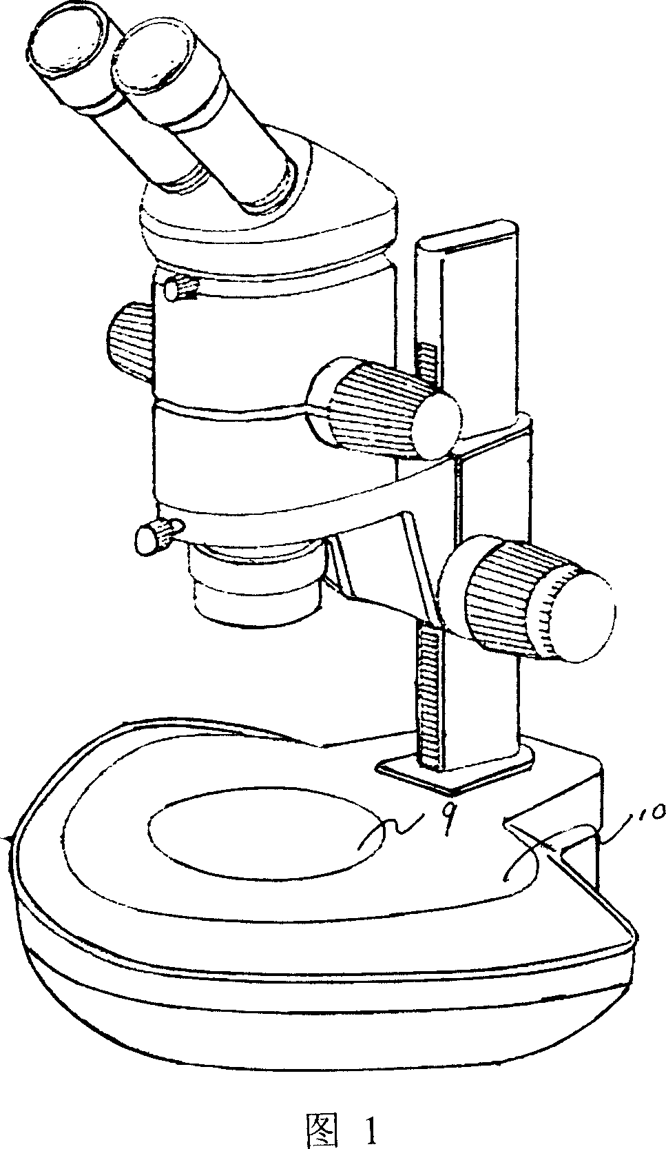
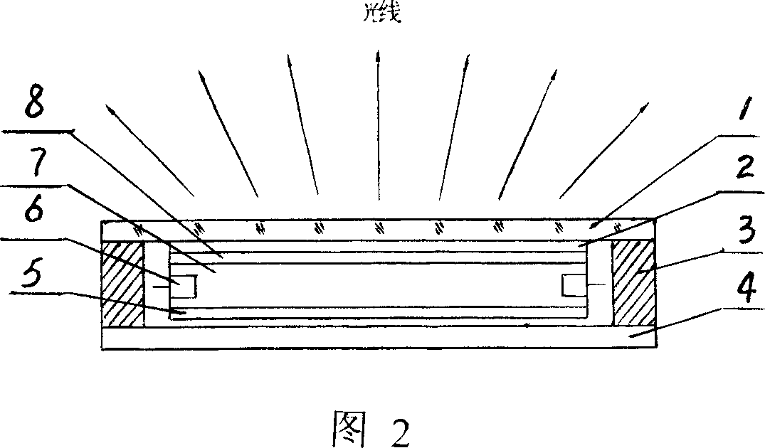
[0008] Embodiment 1: with reference to accompanying drawing 1 and 2. The microscope bottom light source composed of LED backlight board, the microscope bottom light source 10 adopts LED backlight board 9 . The light enhancement film 2 is an existing product and is located on the diffusion film 8 in the LED backlight panel 9, and the diffusion film 8 is an existing product, which will not be described here. The transparent protective glass 1 is positioned on the light-enhancing film 2, and the bottom plate 4 is a black plate and positioned on the reflective film 5, which is an existing product and will not be described here. The manufacturing process of LED backlight plate 9 is the prior art, that is, it is made of reflective film 5, LED (light emitting diode) 6, light guide plate 7, and diffusion film 8. ) is located at the side of the light guide plate 7 . The LED backlight panel 9 is assembled in the frame 3 . LEDs (Light Emitting Diodes) are white or red, green, blue, am...

Embodiment 2

[0009] Embodiment 2: On the basis of Embodiment 1, the LED backlight board power leads are connected to a light controller. The light controller is a prior art and can control the brightness and chromaticity of the backlight light source board.


PUM


Abstract

A microscope bottom lighting source formed by LED back light plate is featured as setting light intensification film on diffusion film in LED back light plate for obtaining uniform-lighting with brightness and color both being able to be adjusted.

Description

technical field [0001] The invention relates to a microscope bottom (bottom) lighting source composed of an LED backlight board, belonging to the field of microscope bottom (bottom) lighting source manufacturing. Background technique [0002] The existing microscope bottom (lower) illumination source, in terms of structural design, adopts incandescent lamps, light-emitting light sources composed of single or multiple LEDs (light-emitting diodes), and the light emitted by these light sources is irradiated on the frosted glass to form uniform illumination. Light. Its shortcomings: 1. Frosted glass is not a good cosine radiation material, and it will not form uniform light with good performance. There are still spots opposite to incandescent lamps or LEDs (light-emitting diodes), which directly affect the observation effect of the microscope. 2. Due to such a structure, there is a gap of more than 30mm between the light source and the frosted glass, so that the thickness of th...

Claims


Application Information

Patent Timeline
IPC IPC(8): G02B21/06
Inventor 蔡勇
Owner 蔡勇
Why Eureka
Try Eureka