Potentiometer

A potentiometer and electrical connection technology, applied in the field of potentiometers, can solve problems such as inflexibility, expensive methods, and expensive potentiometers

Inactive Publication Date: 2012-02-22
ABB PATENT GMBH
View PDF0 Cites 2 Cited by
  • Summary
  • Abstract
  • Description
  • Claims
  • Application Information

AI Technical Summary

Problems solved by technology

[0005] The hitherto known methods are very expensive and inflexible due to the need for laser adjustment
Potentiometers of this type known to have high precision are relatively expensive

Method used


Image

  • Potentiometer
  • Potentiometer
  • Potentiometer

Examples


Embodiment Construction

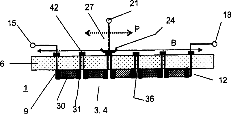
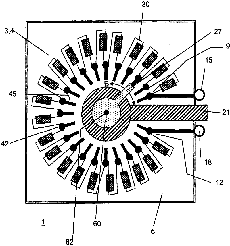
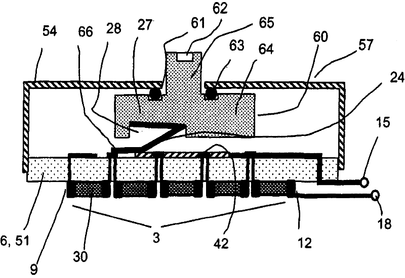
[0039] figure 1A potentiometer 1 is shown with a first potentiometer connection 15 , a second potentiometer connection 18 and a third potentiometer connection 21 . Arranged on the underside of the carrier plate 6 is an array 4 of resistive elements 30 in the form of a series circuit. The resistance element 30 is designed as an SMD component. They each carry a connecting piece 31 made of solder material at the ends of the cuboidal resistor body.

[0040] Electrically conductive leads lead from the connecting piece 31 of each resistor element 30 to the opposite side of the carrier plate 6 . There, the conductive leads of two adjacent resistance elements are electrically connected in electrical connection points 42 . The conductive leads thus form means for electrically connecting the components of the resistor array 3 with the sliding contacts within the adjustment range of the tap 27 . In this way, a series circuit of the resistor circuit 3 is produced between the first fre...


PUM


Abstract

The potentiometer (1) has a carrier plate (6) e.g. printed circuit board, carrying a resistance strip (3). The strip is formed from a resistor arrangement (4) of electrically interconnected discrete resistor units (30) e.g. surface mount device (SMD) components, with preset resistance values. A measuring tap (27) carries a sliding contact that is electrically connected with an electrical connection point (42) of the resistor arrangement along movement track of the strip by an electric connection device in an adjusting position of the tap. The sliding contact is formed as a ridge or brush.

Description

technical field [0001] The invention relates to a potentiometer according to the preamble of claim 1 . A potentiometer of this type has three potentiometer contacts and a carrier board carrying the resistor circuit. Free ends of the resistor circuit are connected to the first and second potentiometer connections. Furthermore, a potentiometer of this type has a tap which carries a sliding contact and which is connected to a third potentiometer terminal. Background technique [0002] Such potentiometers are known in principle from the prior art as adjustable resistors. Its basic structure and methods of application are described, for example, in the textbook "Ekbert Hering, Klaus Bressler, Elektronik für Ingenieure, VDI Verlag Düsseldorf, 1992, Chapter 2.2.4". [0003] In order to produce a potentiometer of this type, the carrier is coated with one or more resistive substances according to hitherto known methods. The resistive substance forms a continuous resistive coating...

Claims


Application Information

Patent Timeline
Patent Type & Authority Patents(China)
IPC IPC(8): H01C10/16H01C10/32H01C1/12
CPCH01C10/48
Inventor R·-R·D·易S·-G·Q·王J·-Z·Y·姜G·尼沃纳
Owner ABB PATENT GMBH
Why Eureka
Try Eureka