Method for optimizing motion inspecting result

A motion detection and motion technology, applied in color TV parts, TV system parts, signal generators using optical-mechanical scanning devices, etc., can solve problems such as motion misjudgment, influence, and influence on motion detection results , to enhance image quality, eliminate false detections, and reduce random noise

Active Publication Date: 2007-11-21
ARKMICRO TECH
View PDF0 Cites 5 Cited by
  • Summary
  • Abstract
  • Description
  • Claims
  • Application Information

AI Technical Summary

Problems solved by technology

There are two reasons for this phenomenon. One is that there is a lot of noise in the analog video signal, and motion detection is very sensitive to noise, so many points are misjudged due to the influence of noise. Although the noise reduction unit can reduce the noise However, it is impossible for any noise reduction system to completely eliminate noise. At the same time, noise reduction will have more or less impact on the original image, and these side effects will indirectly affect the motion detection results.
Another reason is that most motion detection algorithms have more or less defects, and motion misjudgments often occur in some specific situations.

Method used


Image

  • Method for optimizing motion inspecting result
  • Method for optimizing motion inspecting result
  • Method for optimizing motion inspecting result

Examples


Embodiment Construction

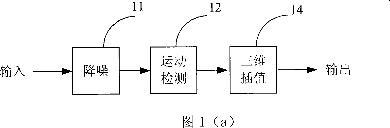
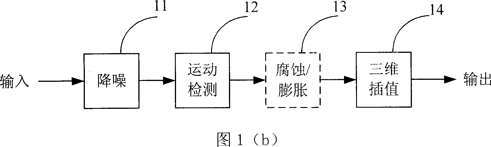
[0055] In order to enable those skilled in the art to better understand and implement the present invention, the method of the present invention will be described in more detail below in conjunction with the accompanying drawings.

[0056] As shown in accompanying drawing 1 (b), erosion / expansion unit 13 is added after motion detection unit 12, and motion detection result first passes through corrosion process, and here, some isolated motion points will be eliminated from static background, and the other of corrosion One function is to eliminate false detections caused by the existence of horizontal boundaries (this is one of the common misjudgments in motion detection), and the erosion results are then processed by expansion, and adjacent large areas with the same motion state will be fused into a whole.

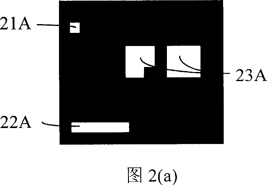
[0057] The white area in Figure 2(a) represents the moving part, and the black area represents the static part. Figure 2(b) shows the result of Figure 2(a) after corrosion,...


PUM


Abstract

The method comprises: newly adding an erosion / dilation unit between the motion detection unit and the 3D interpolation unit; removing the miss-estimation and noise from the motion result by calculating the motion value of 1D or 2D neighborhood of current detection point and by making erosion for the motion value of point to be detected; interfusing the identical areas by making dilation for the erosion value of 1D or 2D neighborhood of current detection point.

Description

technical field [0001] The invention belongs to the technical field of de-interlacing in digital video processing, and in particular relates to a method for optimizing motion detection results when performing de-interlacing processing on interlaced television signals. Background technique [0002] Most of the existing video display systems (such as computers, digital TVs, etc.) receive progressive scan video signals, but the video signals transmitted in most consumer video applications are interlaced scan signals. For example, the most commonly used NTSC and PAL TV signals are interlaced scanning signals. The interlaced scan signal consists of a series of image "fields", and each field contains only half of the effective lines of a complete video frame. Therefore, this display method will bring the disadvantages of low vertical resolution and large-area flickering, and it is easy to cause visual acuity when viewed for a long time. Fatigue, progressive...

Claims


Application Information

Patent Timeline
Patent Type & Authority Applications(China)
IPC IPC(8): H04N5/44H04N7/01H04N11/20G06T7/20
Inventor 李琛刘芳田锦程常军锋刘俊秀张亚国石岭
Owner ARKMICRO TECH
Why Eureka
Try Eureka