
Method and device for transmitting concrete by concrete pump vehicle

A concrete pump truck and a technology for pumping concrete, which is applied in the processing of building materials, construction, building structure, etc., can solve the problems of affecting construction efficiency, small distance, accelerated pipeline wear, etc., to improve work stability, improve Construction efficiency and length reduction effect

Inactive Publication Date: 2007-11-28
董连城
View PDF0 Cites 10 Cited by
  • Summary
  • Abstract
  • Description
  • Claims
  • Application Information

AI Technical Summary

Problems solved by technology

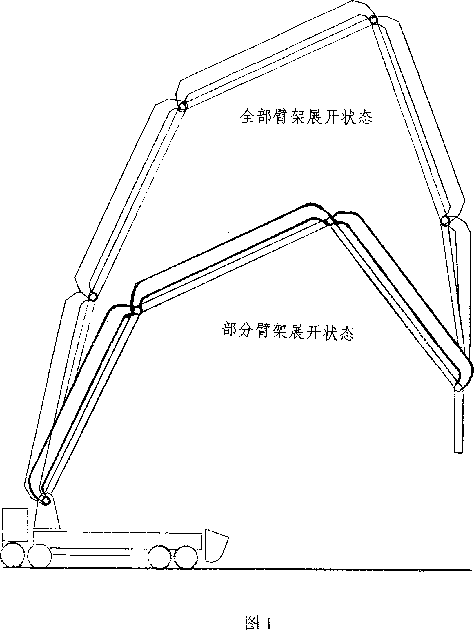
However, in most construction operations, the pumping concrete elevation or span distance is not large, and it is not necessary to fully expand the tens of meters of jib and jib piping
However, in the current concrete pump truck, the discharge outlet is only provided at the end of the boom piping, so the boom has to be extended tens of meters.
The concrete must be piped through all booms before it can be pumped to the place of use, otherwise the concrete pumping operation cannot be carried out
[0004] In this case, the pumping mechanism must consume a certain amount of vehicle engine power to provide a higher pumping pressure to meet the requirements of pumping concrete; the concrete flowing in the pumping pipeline not only generates greater pressure on the pipeline, but also accelerates the flow In addition, no matter whether the construction space is allowed or not, the concrete pump truck must try to expand the boom of tens of meters, which not only affects the construction efficiency, but also reduces the stability of the construction work of the concrete pump truck

Method used


Image

  • Method and device for transmitting concrete by concrete pump vehicle
  • Method and device for transmitting concrete by concrete pump vehicle
  • Method and device for transmitting concrete by concrete pump vehicle

Examples


Embodiment Construction

[0020] The present invention will be further described below in conjunction with the accompanying drawings.

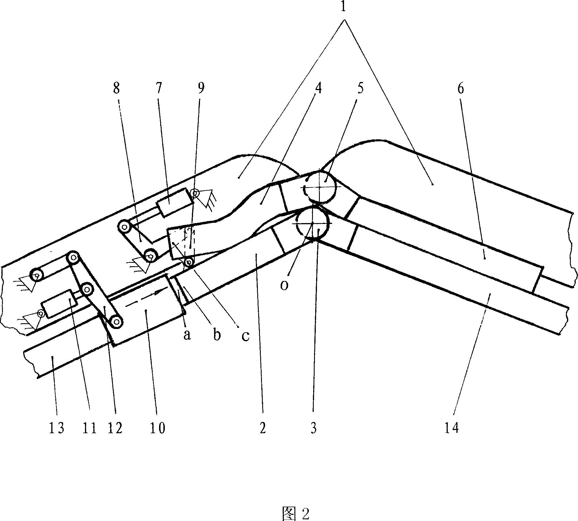
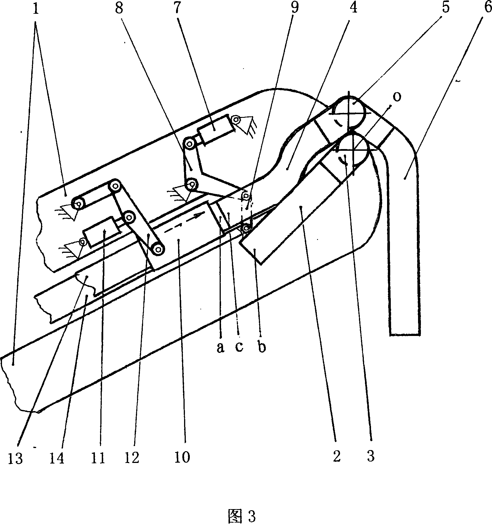
[0021] When the concrete pump truck is carrying out long-distance pumping concrete construction work, the pipe switching cylinder 7 pushes the rocker arm 8, so that the connecting rod 9 pulls the rigid pipe switching member in a direction centered on the common axis O of the boom hinge shaft and the boom elbow 3. Turn clockwise to connect the inlet b of the switchable boom pipe 2 in the pipe switching member with the outlet a of the front boom pipe 13 . The sheath push-pull oil cylinder 11 pushes the rocker 12 so that the pipeline is connected to the sheath pipe 10 to reliably connect the a and b nozzles. At this time, the concrete pump truck is in the working state of long-distance pumping concrete. The pumped concrete passes through the front boom pipe 13, the outlet a of the front boom pipe 13, the inlet b of the switchable boom pipe 2, the switchable boom pipe 2, ...


PUM


Abstract

The invention provides a method for pumping concrete in concrete pump truck and the device. The pumping distance of prior concrete pump truck in most construction occasions is not big but only one discharge port is set at the end of fitting pipe of arm frame in the arm frame with several decameters. So in construction all arm frames must be unfolded and by adopting high-pressure pumping, concrete passes through all fitting pipes of arm frame. Not only power is consumed and abrasion is enlarged but also efficiency and stability are decreased. Aiming at the lack of concrete pump truck existing in pumping work process, the invention provides that concrete assistant discharge device is set on the arm frame of concrete pump truck; according to the construction distance of pumping concrete fitting pipes of arm frame is switched and all or part fitting pipes of arm frame are selected to carry the construction operation of pumping concrete out. The invention can unfold proper arm frame according to the requirement and make use of corresponding fitting pipe of arm frame to construct work of pumping concrete so as to achieve purposes that the pumping pressure is decreased; energy consumption is decreased; pipe abrasion is decreased; work efficiency and stability of pumping operation are improved.

Description

technical field [0001] The invention relates to a concrete pump truck, in particular to a concrete pumping method and device for a concrete pump truck. Background technique [0002] Concrete pump trucks, which are now widely used in infrastructure construction, need to expand the boom when implementing concrete pumping construction operations. Under the high pressure of the pumping system, the concrete is pumped to the place of use through the boom pipe installed on the boom. Boom piping consists of pumping pipes, pumping elbows and discharge hoses. The hinge shaft and pumping elbow between the booms on the same axis can make the tens of meters of boom and boom piping expand or retract under the control of the boom cylinder. [0003] When the concrete pump truck implements the pumping operation of high-rise or large span, it is necessary to expand the boom of tens of meters. However, in most construction operations, the pumping concrete elevati...

Claims


Application Information

Patent Timeline
Patent Type & Authority Applications(China)
IPC IPC(8): E04G21/04
Inventor 董连城
Owner 董连城
Learn More