Optical distance measuring device and manufacturing method therefor

A distance measuring device and a manufacturing method technology, which are applied in the field of optical distance measuring devices, can solve problems such as the failure of the second optical path, enlargement of the distance measuring device, improper structure, etc., and achieve suppression of light leakage, high distance measurement accuracy, Improve the effect of optocoupler

Inactive Publication Date: 2007-11-28
SHARP KK
View PDF3 Cites 11 Cited by
  • Summary
  • Abstract
  • Description
  • Claims
  • Application Information

AI Technical Summary

Problems solved by technology

However, in the conventional distance measuring devices disclosed in the aforementioned Documents 3 to 5, there is no mention of the thermal expansion of the second optical path.
In addition, since the above-mentioned second optical path is composed of separate optical elements, the distance measuring device becomes large, and it becomes an inappropriate structure when used in electronic equipment.

Method used


Image

  • Optical distance measuring device and manufacturing method therefor
  • Optical distance measuring device and manufacturing method therefor
  • Optical distance measuring device and manufacturing method therefor

Examples


no. 1 approach

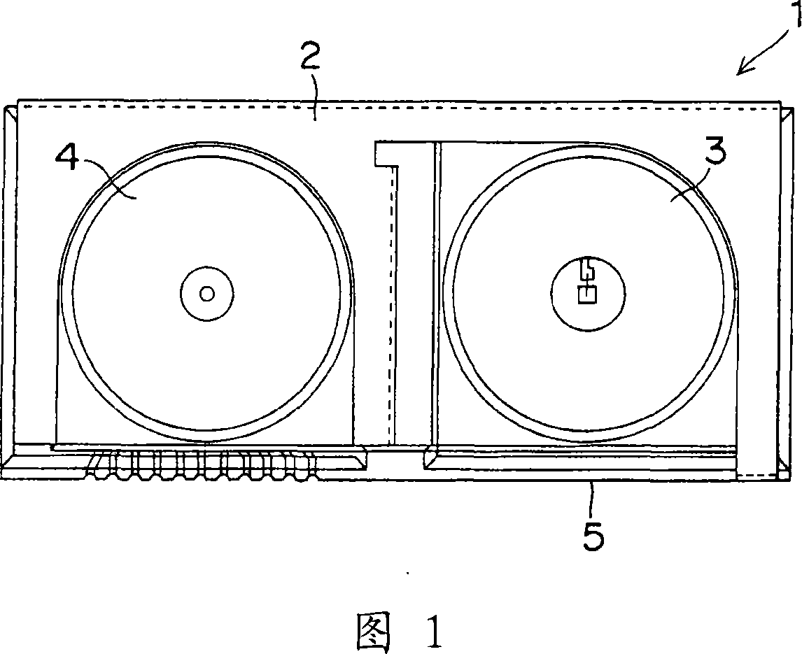
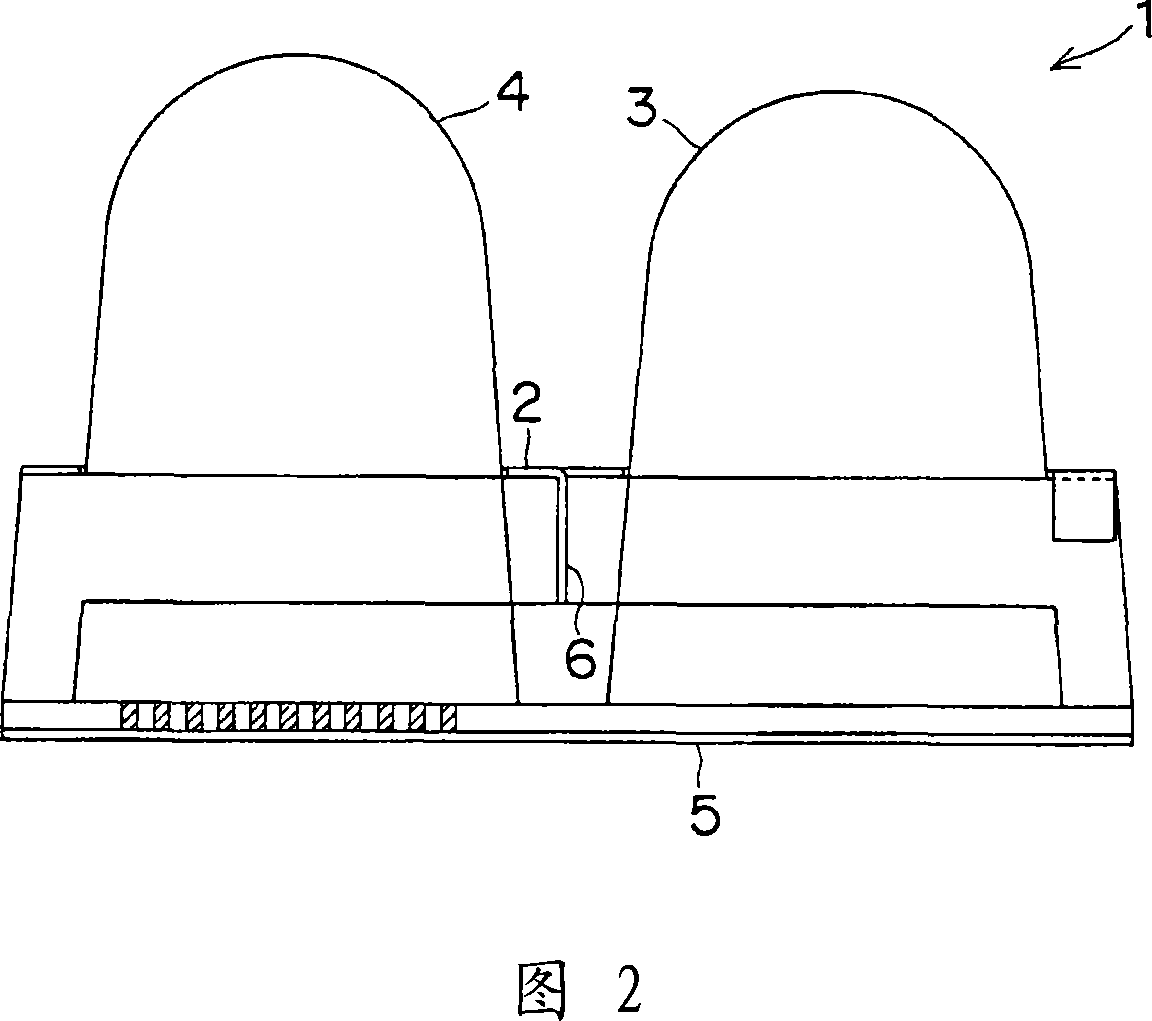
[0073] FIG. 1 is a plan view of an optical distance measuring device 1 according to the present embodiment. In addition, FIG. 2 is a side view of the optical distance measuring device 1 shown in FIG. 1 . In addition, this optical distance measuring device 1 uses a first optical path in which the light emitted from the light emitting element is reflected by the distance measuring object and detected by the light receiving element, and the light emitted from the light emitting element is not reflected by the distance measuring object. The second optical path detected by the above-mentioned light-receiving element is especially suitable for small-sized optical ranging of electronic equipment such as special-purpose automatic machinery or mechanical contacts with small mechanical contacts that need to detect obstacles, or non-contact control equipment. device.

[0074]The present optical distance measuring device 1 has a structure shielded by a shielding case 2 so that electrical...

no. 2 approach

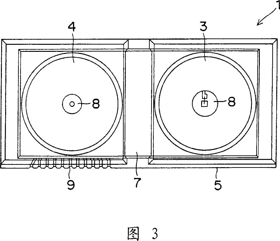
[0100] In the optical distance measuring device 1 of the above-mentioned first embodiment, as shown in FIG. The light from the light receiving element 11 generates light interference, and the value of the SN ratio is deteriorated by the light interference, thereby increasing the measurement error. In addition, since most of the light passing through the second optical path 18 enters the above-mentioned end surface of the light receiving element 11, the light coupling efficiency of the second optical path 18 decreases. Therefore, the present embodiment relates to an optical distance measuring device in which, in particular, the optical coupling efficiency of the second optical path is further improved, and distance measurement can be performed with high accuracy even when the temperature changes greatly.

[0101] Hereinafter, the optical distance measuring device according to this embodiment will be described in detail focusing on the differences from the first embodiment descr...


PUM


Abstract

The present invention provides an optical distance measuring device and manufacturing method therefor. In the optical distance measuring device of the invention, a second optical path is formed by a transparent resin formed in a region where a light emitting element and a second light receiving part are connected directly to each other. As the temperature increases, the length of the optical path increases while its refractive index decreases, so that the optical path length itself becomes generally constant. Therefore, the length of the second optical path can be kept generally constant independently of temperature. Further, a first light receiving part for a first optical path and a second light receiving part for the second optical path 18 are formed in one identical light receiving element. Therefore, characteristic variations of the first light receiving part and the second light receiving part due to temperature can be reduced. This optical distance measuring device can achieve high distance measuring accuracy even under environments of intense temperature changes.

Description

technical field [0001] The present invention relates to an optical distance measuring device and its manufacturing method. The distance to the distance-measuring object is measured by the two optical paths of the second optical path reaching the light receiving element. Background technique [0002] Conventionally, the so-called TOF (Time Of Flight) method is widely known as a distance measuring method in which the round-trip time of light is measured to calculate the distance to the measurement object. The ranging method is performed as follows: Since it is well known that the speed of light c is 3.0×10 8 m / s, so by measuring the round-trip time t1, the distance L to the object is calculated using the following formula (1). [0003] L=(c·t1) / 2...(1) [0004] The specific signal processing method in the above-mentioned TOF method has the following various proposals: For example, the distance measuring device disclosed in (Japanese) Patent Application Publication No. 6-186...

Claims


Application Information

Patent Timeline
Patent Type & Authority Applications(China)
IPC IPC(8): G01S17/10G01S7/48
Inventor 石原武尚民长隆之
Owner SHARP KK
Why Eureka
Try Eureka