Image display device

一种显示部分、图案化的技术,应用在辨认装置、静态指示器、光学等方向,能够解决引导线123消失、其它事物没有公开、上升等问题

Inactive Publication Date: 2007-12-05
NEC CORP
View PDF1 Cites 13 Cited by
  • Summary
  • Abstract
  • Description
  • Claims
  • Application Information

AI Technical Summary

Problems solved by technology

As a result, there is a possibility that the test electrode 126 made of Cr and the lead wire 123 positioned adjacent thereto disappear.
[0020] Third, there is a possibility that the wiring resistance of the test electrode 126 and the conductive film 123a adjacent thereto increases due to corrosion of the Cr film constituting them
[0021] These phenomena of corrosion and disappearance of the test electrode 126 and its nearby Cr film (i.e., the test electrode 126 and the conductive film 123a) will affect the installation electrode 125 electrically connected to the test electrode 126 through the conductive film 123a, thereby causing display abnormalities
[0022] Furthermore, with the prior art image display device disclosed in Publication No. 2005-121976, although corrosion of metal wiring having relatively low corrosion resistance is considered, nothing else is disclosed
There is no test electrode 126 related to the prior art COG type LCD device shown in FIGS. 1 and 2
In addition, of course, there is no mention of the above-mentioned problems that occurred in the test of the display section 111 and countermeasures to solve them

Method used


Image

  • Image display device
  • Image display device
  • Image display device

Examples


no. 1 example

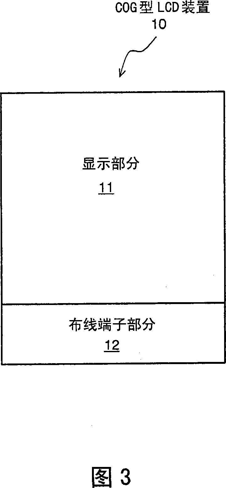
[0066] An image display device according to a first embodiment of the present invention is shown in FIGS. 3 to 6 configured as a COG type LCD device 10 .

[0067] As shown in FIG. 3 , the LCD device 10 according to the first embodiment includes a display portion 11 and a wiring terminal portion 12 formed outside the display portion 11 adjacent thereto. The display section 11 is a section or area for displaying images, and includes a plurality of pixels arranged in a matrix array. The wiring terminal portion 12 is a portion or region in which a driver IC for driving liquid crystals is mounted and connected to an FPC.

[0068] Schematic structures of the display section 11 and the wiring terminal section 12 are shown in FIG. 4 . The display section 11 includes: a TFT substrate 20 , a color filter (CF) substrate 30 , and a liquid crystal 40 arranged between the two substrates 20 and 30 . The TFT substrate 20 includes a glass plate 21 , and TFTs and pixel electrodes (both not sh...

no. 2 example

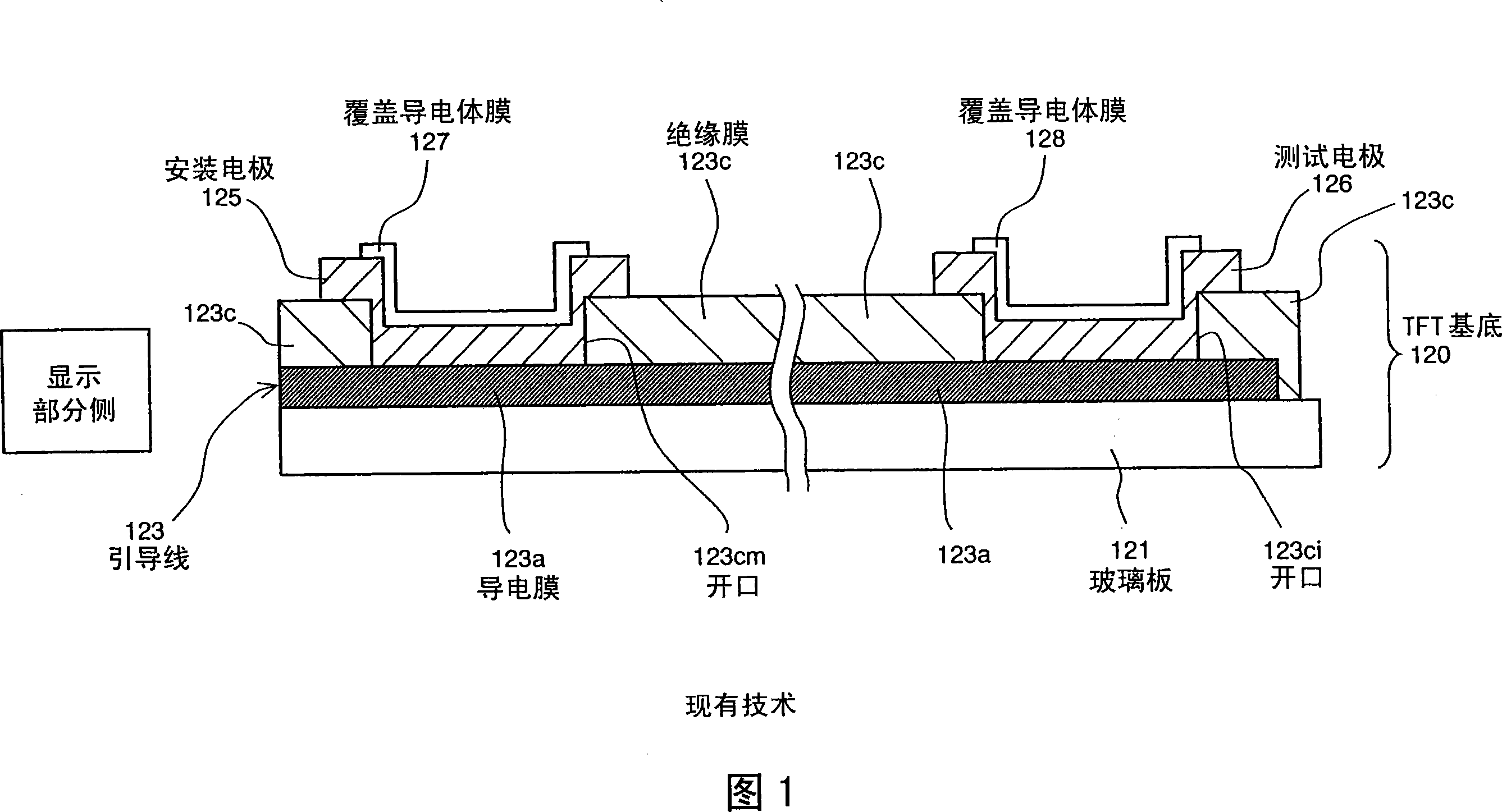
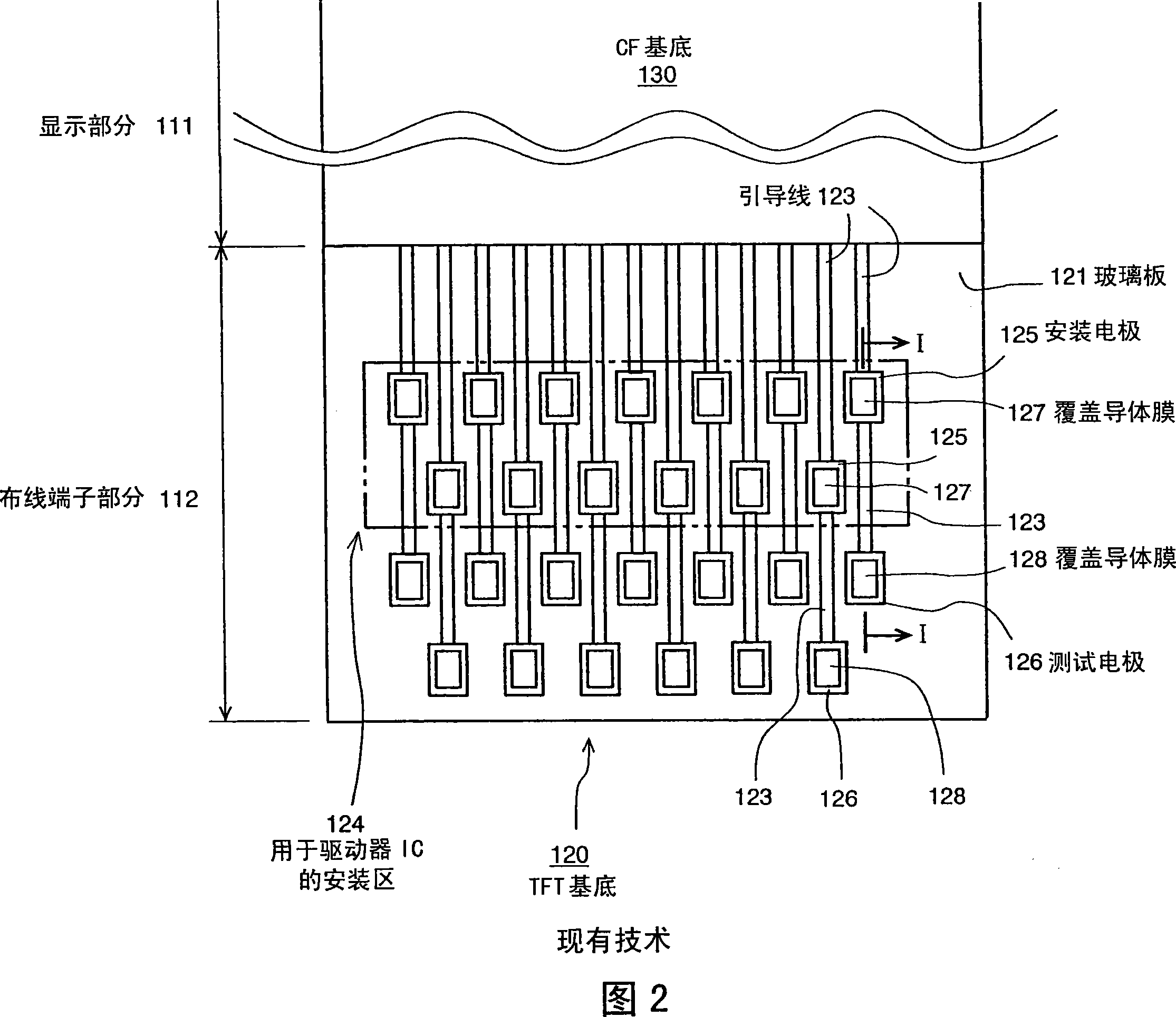
[0094] 7 is an enlarged partial sectional view similar to FIG. 6, showing a schematic structure of lead wires 23 formed in wiring terminal portion 12 of a COG type LCD device as an image display device according to a second embodiment of the present invention.

[0095] The lead wire 23 in the second embodiment has the same structure as that of the lead wire 23 in the first embodiment described above, except that three test electrodes 26-1, 26-2, and 26-3 are arranged instead of for each The test electrode 26 of the electrode 25 is installed. It can be said that two additional test electrodes 26-2 and 26-3 are added to the test electrode 26-1 corresponding to the test electrode 26 in the first embodiment. Differences from the first embodiment will be mainly explained below.

[0096] As shown in FIG. 7, the lead wire 23 includes a patterned conductive film 23a having a narrow strip shape, three patterned conductive films 23b-1, 23b-2, and 23b-3 having an island shape, and a pat...


PUM


Abstract

An image display device prevents display abnormality due to the corrosion and / or disappearance of the testing electrodes and / or and the conductive film for leading lines with a simple structure. Leading lines, which are in the wiring terminal section, electrically connect internal wiring lines to a driver IC. Each of the leading line has a mounting electrode and a testing electrode. A patterned first conductive film, which is separate from the testing electrode, connects electrically the mounting electrode to the corresponding internal wiring line in the display section. A patterned connecting conductive film is formed on an insulative film to contact with the mounting and testing electrodes, thereby making electrical interconnection between the mounting and testing electrodes. The connecting conductive film is made of a material (e.g., ITO) whose corrosion resistance is greater than a material (e.g., Cr) for the testing electrode.

Description

technical field [0001] The present invention relates to an image display device, such as a liquid crystal display (LCD) device and a plasma display device. More specifically, the present invention relates to an image display device having a display section including pixels arranged in a matrix array and a wiring terminal section in which a driver IC (Integrated Circuit) or a driving semiconductor device is mounted. Mounting electrodes for mounting the driver IC and test electrodes for testing defects in the display portion are formed in the wiring terminal portion. Background technique [0002] In recent years, LCD devices have been widely used as high-resolution displays or image display devices. Generally, an LCD device includes: a substrate (which will be called a TFT substrate) on which switching elements such as thin film transistors (TFTs) are formed; another substrate (which will be called a CF substrate) on which A color filter, a black matrix, etc. are formed on o...

Claims


Application Information

Patent Timeline
Patent Type & Authority Applications(China)
IPC IPC(8): G02F1/133G02F1/13H01J17/49G02F1/1345G02F1/1368G09F9/00G09F9/30
CPCG02F1/1362G02F1/13458G02F1/1345G02F2001/136254G02F1/136254
Inventor 驹寿学
Owner NEC CORP
Why Eureka
Try Eureka