Fuel cell unit structure and electric pile assembly

A fuel cell unit and fuel technology, applied in the direction of fuel cell grouping, fuel cells, solid electrolyte fuel cells, etc., can solve problems affecting MEA performance, affecting assembly speed, MEA exposure, etc., to reduce fuel and oxidant leakage, reduce Possibility of damage and contamination, effects of improved assembly speed and accuracy

Active Publication Date: 2007-12-05
SUNRISE POWER CO LTD
View PDF3 Cites 21 Cited by
  • Summary
  • Abstract
  • Description
  • Claims
  • Application Information

AI Technical Summary

Problems solved by technology

[0003] However, in the traditional stack assembly process, since the MEA is exposed to the outside, it is susceptible to mechanical damage and is affected by changes in environmental humidity, which affects both the assembly speed and the performance of the MEA.
At the same time, the number of assembly components is relatively large, and the positioning device and method also affect the assembly speed, which is not conducive to the development of batch mechanized automatic assembly
At the same time, there are many sealing surfaces that must be guaranteed during stacking, which is prone to leakage
During the disassembly of the stack and the replacement of electrodes and bipolar plates, the MEA is also vulnerable to damage
[0004] For example, Shanghai Shenli Technology Co., Ltd. (patent number: 03255926.7) applied for an improved fuel cell stack assembly patent, which forms a battery unit, but the MEA is exposed, and it is relatively difficult to store and install.
The US patent Fuel Cell Stack (patent publication: US 2006 / 0068264 A1) mentions a battery assembly (unit cells), but does not disclose the technical realization method of this structure

Method used


Image

  • Fuel cell unit structure and electric pile assembly
  • Fuel cell unit structure and electric pile assembly
  • Fuel cell unit structure and electric pile assembly

Examples


Embodiment Construction

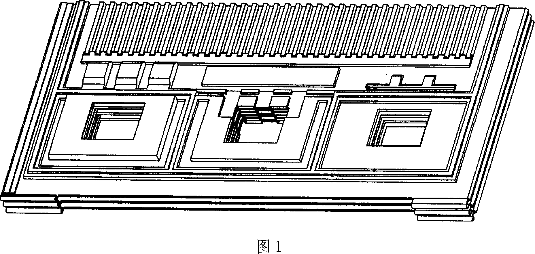
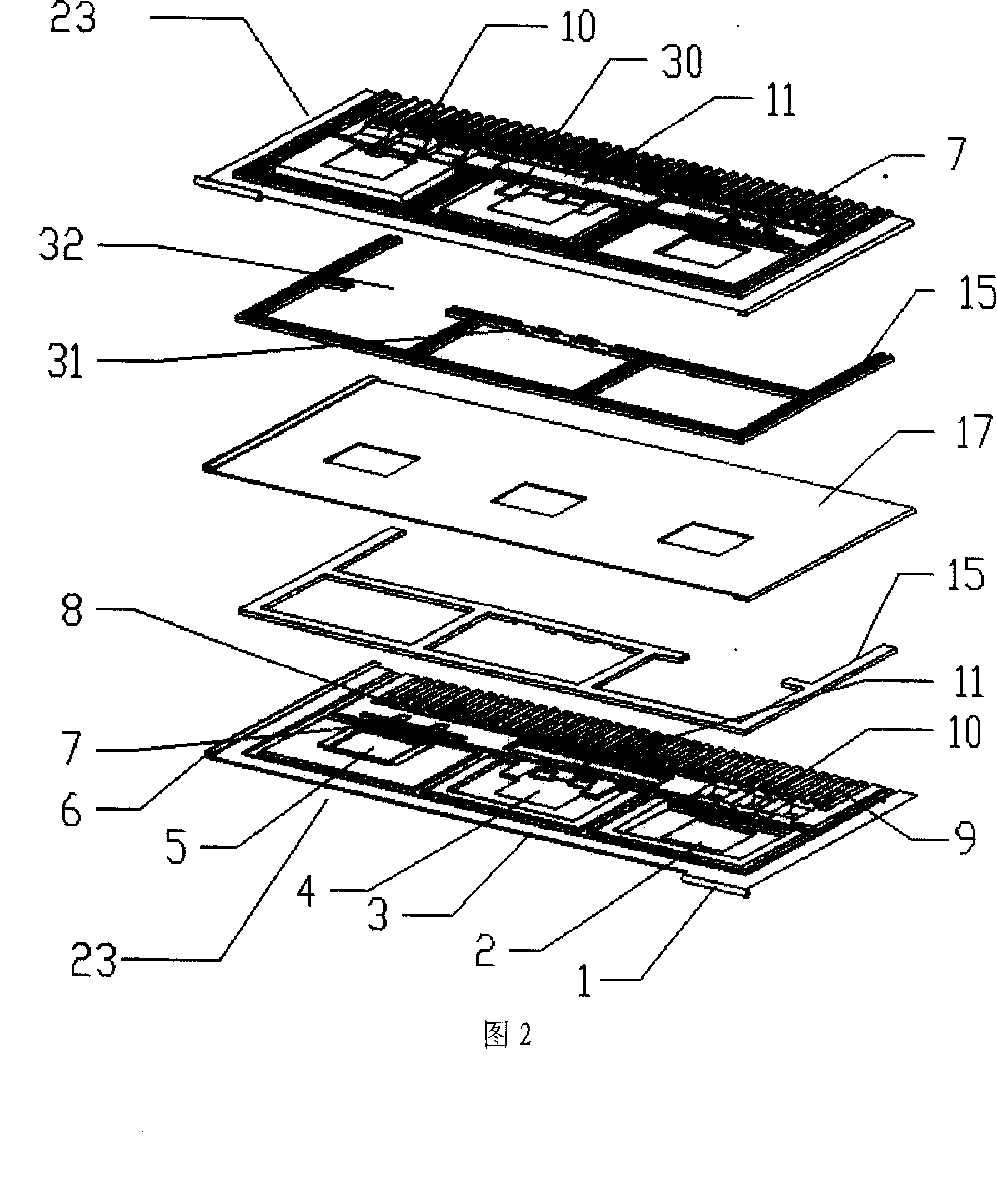
[0040] The unit embodiment of the present invention is shown in Fig. 2 to Fig. 15 . Fig. 1 is a partial perspective view of a multi-cell battery assembled by the unit of the present invention. The flow field form takes parallel grooves as an example, but it is not limited to the flow field structure of parallel grooves. This design is also applicable to other common flow fields.

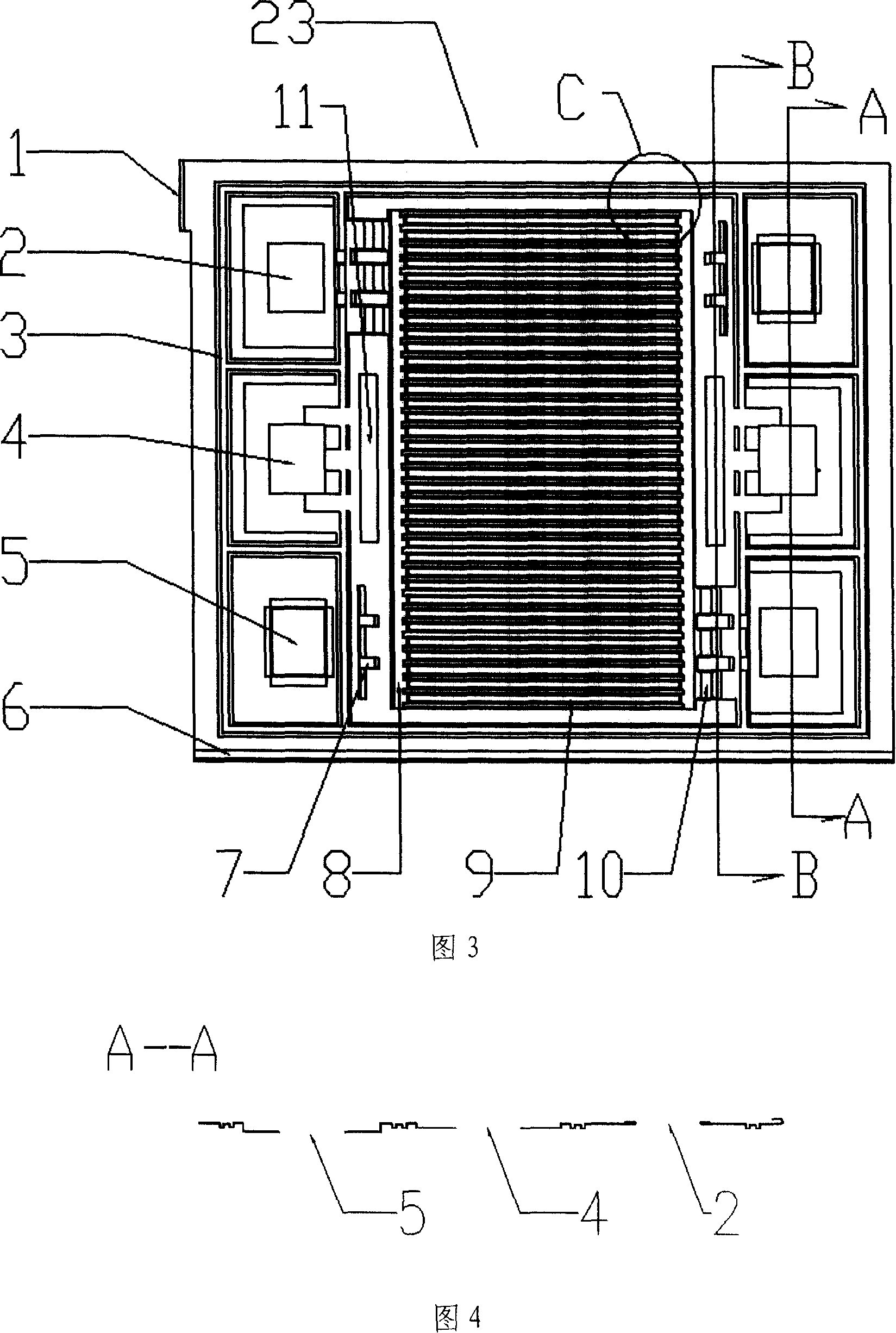
[0041]As shown in Fig. 2 and Fig. 3, the fluid public channels 2 and 5 are used for the delivery of fuel and oxidant, and the MEA17 is encapsulated on the inside of two metal plates 23, and the side of the metal plate 23 in contact with the MEA17 forms the fluid of oxidant or fuel Channel, that is, the inner side of the unit structure, there is a sealing inner glue line 15 between the electrode MEA17 and the metal pole plate 23, and a gap 32 is provided on the inner glue line 15 at the position of the bridge 10, and it can also be used between the MEA17 and the metal pole plate 23 The adhesive secur...


PUM


Abstract

The invention relates to the combination cell structural design which is sealed by the fuel cell metal pole plate and the membrane electrode module, concretely is a fuel cell cellular structure and its pile assembly, which includes the mold pressing metal pole plate which has two pieces flow field and the membrane electrode module (MEA). The fuel cell pole plate seals MEA and the seal structure in together and combines the orientation slot and the inspect slot to form the fuel cell unit. The structure formed the only unit module of the generate electric element when groups the pile, reduced the component quantity of the pile assembly, enhanced the assembly speed and the size stability of the pile, and reduced the replacement damage of MEA when assembles, is advantageous in enhances battery's performance, suits the mechanized production of the pole plate and the pile assembly.

Description

technical field [0001] The invention relates to the combined unit structure design of fuel cell metal pole plate and membrane electrode assembly packaging, in particular to a fuel cell unit structure and stack assembly thereof, which is suitable for hydrogen proton membrane fuel cells. Background technique [0002] Each battery cell of the fuel cell is composed of a cathode and anode plate with a flow field and a membrane electrode assembly (MEA) in the middle, and has a cooling structure. Taking the hydrogen proton membrane fuel cell as an example, in terms of the design of the anode plate and the cathode plate, the two plates are generally designed as a back-to-back structure, and a coolant flow field is formed in the middle to form a bipolar plate structure, and then connected with the MEA and the sealing line and other components are stacked alternately to form a stack of multiple cells. There is also an electric stack in which the MEA is fabricated on the outside of th...

Claims


Application Information

Patent Timeline
Patent Type & Authority Applications(China)
IPC IPC(8): H01M8/10H01M8/24H01M8/1004
CPCY02E60/521Y02E60/50Y02P70/50
Inventor 盛武林侯明明平文
Owner SUNRISE POWER CO LTD
Why Eureka
Try Eureka